Bi-directional current limiting circuit?

crutschow

Joined Mar 14, 2008
38,813
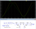
If needed, below is the LTspice sim of a relatively simple circuit using 2 PNP transistors and 2 back-to-back P-MOSFETs to give a bi-directional, current-limit circuit:
It works, because MOSFETs conduct equally well in both directions when ON (P-MOSFET gates at ground potential).

The current limit is approximately 0.6V/Rlimit.
Rlimit1 determines the load current limit, and Rlimt2 determines the charge current, here giving a limit of ≈ 3A for the charge current (yellow trace, positive current) and ≈ 6A for the load/start current.

M1 and M2 can be just about any P-MOSFET with at least a 20V rating, and an on-resistance of ≤20mΩ.
The MOSFETs must be mounted on a heat-sink with no more than about a 15°C/W thermal resistance.
1790384839511.png
 

kiroma

Joined Apr 30, 2014
210
If needed, below is the LTspice sim of a relatively simple circuit using 2 PNP transistors and 2 back-to-back P-MOSFETs to give a bi-directional, current-limit circuit:
It works, because MOSFETs conduct equally well in both directions when ON (P-MOSFET gates at ground potential).

The current limit is approximately 0.6V/Rlimit.
Rlimit1 determines the load current limit, and Rlimt2 determines the charge current, here giving a limit of ≈ 3A for the charge current (yellow trace, positive current) and ≈ 6A for the load/start current.

M1 and M2 can be just about any P-MOSFET with at least a 20V rating, and an on-resistance of ≤20mΩ.
The MOSFETs must be mounted on a heat-sink with no more than about a 15°C/W thermal resistance.

View attachment 371679
Very nice job.
I wouldn't have done this so elegant like that, I would have used diodes.
The only warning I'd give is that the Rlimit2*max current limited by Rlimit1 (ie. the backwards voltage VBE on Q2 produced by limiting the current on Rlimit1) shouldn't go past 5 V. The same applies for the complementary, Rlimit1*max current limited by Rlimit2 shouldn't be greater than 5 V. This can happen when I1 is very different from I2.
I don't think that's going to happen, but it's important to consider this.
 

kiroma

Joined Apr 30, 2014
210
I just realized something.
The circuit @crutschow made is a moderate in terms of complexity of a solution, of course you can always make it nearer to perfection. It's very low output impedance in both ways and it doesn't consume not even a whole mA, it's considered low power.

But it's still one battery charging the other via linear voltage drop. The excess voltage times the current is dissipated in form of heat. A better solution would be if TS put a toggle switch on the radio power input. So he/she would toggle between batteries, giving the ability to discharge the secondary battery listening to the radio and still toggle very fast to listen to what the radio announcer said next, or finish listening to the song that was playing when the battery dies. (Also, it's a matter of taste how you'd like for the operation to be).
But then comes the question, when he/she will charge the battery? Another switch needed. So this option doesn't seem too good. What happens if he/she forgets to switch to main battery when the car is on? The battery drains if the radio is on.

A better solution (I think) (but not perfect yet):
It's possible to put just one switch, so the radio is permanently on the second battery and the switch just enables the charging. But this also requires rewiring the radio power input. When TS turn off the car, he/she switch the charging off and continue with the radio on. If/when the battery dies, there's the decision of whether you want to charge the second battery with the main one, or, of course, turn on the engine.

Sorry if my skill with the language is a barrier in this post, it's late in the night post 44 hour work-week. I tried my best.
 
Last edited:

crutschow

Joined Mar 14, 2008
38,813
I wouldn't have done this so elegant like that, I would have used diodes.
Borrowing the dictum from Einstein, that's too simple.
The diode drop would prevent the proper charging voltage from fully charging the battery, so you need a little more elegance. ;)
The only warning I'd give is that the Rlimit2*max current limited by Rlimit1 (ie. the backwards voltage VBE on Q2 produced by limiting the current on Rlimit1) shouldn't go past 5 V.
An added reverse diode across the base-emitter junction will limit the reverse voltage to a safe value, if that could be a problem.
Such a diode, particularly if it's a Schottky, would also reduce the Rlimit resistor dissipation from the reverse current, a win-win.
 

kiroma

Joined Apr 30, 2014
210
Borrowing the dictum from Einstein, that's too simple.
The diode drop would prevent the proper charging voltage from fully charging the battery, so you need a little more elegance. ;)
But if it's a Schottky, it will be 0.3 V.

An added reverse diode across the base-emitter junction will limit the reverse voltage to a safe value, if that could be a problem.
Yes.

Such a diode, particularly if it's a Schottky, would also reduce the Rlimit resistor dissipation from the reverse current, a win-win.
I didn't understand this part. The diode is in series with Rlimit? It can't because would block the other way. In parallel? It can't because it would prevent the BJT from conducting. Where is it?
 

crutschow

Joined Mar 14, 2008
38,813
But if it's a Schottky, it will be 0.3 V.
So if the typical charging voltage from the alternator is 14.6V, it would be reduced to 14.3V.
Certainly will take longer go reach full charge.
I didn't understand this part. The diode is in series with Rlimit? It can't because would block the other way. In parallel? It can't because it would prevent the BJT from conducting. Where is it?
It would be in reverse parallel across Rlimit.
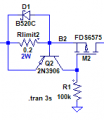
When that circuit is limiting, the diode would then be reverse biased (below for current limiting from left to right current flow).
When the other circuit is limiting the current in the opposite direction, then it would be forward biased to limit the voltage across the transistor base-emitter junction and also Rlimit, reducing its dissipation.

1790444467928.png
 
Last edited:

kiroma

Joined Apr 30, 2014
210
So if the typical charging voltage from the alternator is 14.6V, it would be reduced to 14.3V.
Certainly will take longer go reach full charge.
It would be in reverse parallel across Rlimit.
When that circuit is limiting, the diode would then be reverse biased (below for current limiting from left to right current flow).
When the other circuit is limiting the current in the opposite direction, then it would be forward biased to limit the voltage across the transistor base-emitter junction and also Rlimit, reducing its dissipation.

View attachment 371702
It's obvious, but I didn't see before.
Thank you.
 
Top