Bi-directional current limiting circuit?

crutschow

Joined Mar 14, 2008
38,805
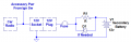
What if he needs to power something more powerful than the power the resistor allows for charging?
The diode carries that current.
Also, I saw years ago that while cranking the engine, the battery drops a good amount of volts, so the diode can fry trying to deliver high current to the main battery.
My assumption is the the accessory socket is not powered when the engine is cranking as most accessory circuits are.
It's a simple circuit but it's not optimal.
Perfection is the enemy of good engineering. :rolleyes:
 

kiroma

Joined Apr 30, 2014
206
The diode carries that current.
My assumption is the the accessory socket is not powered when the engine is cranking as most accessory circuits are.
Perfection is the enemy of good engineering. :rolleyes:
So you're charging through the socket and also the load is across the socket? I don't think I got it right.
If that's what you meant, the load is consuming through the main battery (in parallel with the socket, right?) and charging it via 1 diode with the second battery. Also, if the second battery is somewhat at higher voltage, the diode will fry and also the second battery (smaller) will be damaged because of such high current. Need to be careful to never charge this one above the main one.

I know that perfection is the enemy of good engineering, but I see problems that could happen when someone doesn't know that some scenario might damage components. Every level of complexity gives you more freedom to do more moves that otherwise would be considered a bad thing. That's the price. Sometimes I also take the risk because I know what I've built.
 

crutschow

Joined Mar 14, 2008
38,805
So you're charging through the socket and also the load is across the socket? I don't think I got it right.
The load is the accessory load on the other side of the socket, if that's what you mean.
If that's what you meant, the load is consuming through the main battery (in parallel with the socket, right?) and charging it via 1 diode with the second battery.
Don't understand what you are saying(?).
The diode only conducts when the second battery is powering the accessory equipment.
if the second battery is somewhat at higher voltage, the diode will fry and also the second battery (smaller) will be damaged because of such high current.
Don't think that's a likely scenario.
How would the second battery go to a higher voltage since they are both being charged in parallel at the same time?
 

kiroma

Joined Apr 30, 2014
206
The load is the accessory load on the other side of the socket, if that's what you mean.
Don't understand what you are saying(?).
The diode only conducts when the second battery is powering the accessory equipment.
Don't think that's a likely scenario.
How would the second battery go to a higher voltage since they are both being charged in parallel at the same time?
I think that I understood it wrong, as I suspected.
So, it's a socket that's meant to power the load and other times, charge the battery?

As it's a portable battery, TS might think, let me charge this second battery inside my house because he doesn't want to let the engine on for hours if he already spent all the charge. So the main battery could be discharged a bit by whatever reason, and then the TS charged the second one indoors and then goes and plug them and the diode fry (and the battery gets damaged too).
If the socket for charging could be a different one from the consuming one, would be better IMO.
 

kiroma

Joined Apr 30, 2014
206
Also, if it's exactly the same socket, you can't run your radio while the engine is on, because you're charging the battery, right? So you have to choose between charge the battery or have your things on.
Again, if I understood it right, but I see there's no other way of understanding because you narrowed it down to just this possibility of understanding.
 

crutschow

Joined Mar 14, 2008
38,805
So, it's a socket that's meant to power the load and other times, charge the battery?
Yes, That's it.
TS might think, let me charge this second battery inside my house because he doesn't want to let the engine on for hours if he already spent all the charge.
So with my scheme the TS can't do that.
The usual scenario would be the battery charges during normal driving.
it's exactly the same socket, you can't run your radio while the engine is on, because you're charging the battery, right? So you have to choose between charge the battery or have your things on.
I don't see why you think charging the battery precludes running the radio.
They are connected in parallel so the alternator can do both at the same time, no?
 

kiroma

Joined Apr 30, 2014
206
I don't see why you think charging the battery precludes running the radio.
They are connected in parallel so the alternator can do both at the same time, no?
I thought the radio was in parallel with the socket, when it's unplugged from the main battery (I thought it was plug in to charge, unplug, plug to the radio).

I didn't understand how the radio would be in parallel with the main and second batteries, unless they are both being discharged by the radio at all times, except for the cranking. But then it's just another battery in parallel, better to just buy a same-sized battery as the main one and put in parallel, no?
Edit: Because it's going to discharge both batteries with no 0% warning. It's both harmful for the batteries and also troublesome for the TS away from home.
 

crutschow

Joined Mar 14, 2008
38,805
I didn't understand how the radio would be in parallel with the main and second batteries
The radio is the built-in normal car radio connected to the accessory power circuit, not a separate device.
(See below):
Because it's going to discharge both batteries with no 0% warning.
No.
When he's using the second battery, the ignition key is off and the accessory power from the main battery is disconnected.

1790197828477.png
 
Last edited:

kiroma

Joined Apr 30, 2014
206
The radio is the built-in normal car radio connected to the accessory power circuit, not a separate device.
(See below):
No.
When he's using the second battery, the ignition key is off and the accessory power from the main battery is disconnected.

View attachment 371610
This can be it for the TS, but my car, anytime I press the power button (radio), it turns on, no matter what the ignition key position is.
 
One choice that might be acceptable is to simply connect the second battery to the Accessory circuit directly. It would charge when the engine was running and power the accessories at any time, engine on or off. Possibly have a series switch to diconnect when not wanting to power the ACC items withthe engine off.
 

Thread Starter

LikeTheSandwich

Joined Feb 22, 2021
215
" radio and stuff " are self-limiting. They draw only the current they need. I don't see a need for a current limiter. What am I missing?

ak
Well mainly if the battery gets too low, and then I start up the engine, it could try to charge that accessory battery at the 80 amp maximum output of my alternator. But that's going to fry my socket. So I need to limit the charging current in that direction. I need to limit power the other way so that during starting it's not going to fry the socket trying to pull power from the accessory battery.

What is the maximum current need to be drawn from the leisure battery?
I haven't measured the drain yet but I can't imagine it's more than a couple of amps. The battery will easily last three or four days and still start up, but I think like 5 days is hit or miss, and 6 days is definitely too long.

But how will you stop the drain from the main battery when the secondary battery is connected?
The batteries will be in parallel and both will discharge from the load.
Correct, it will not stop the parasitic drain, although I could get a quick disconnect for the main battery or even a remote disconnect. But even without that, if I could double my power, then that would mean I would only be partially draining the main battery, especially if I get a power dense deep cycle battery as my backup, or a large lithium battery or something like that.

Good ideas.
But I think we've established that bi-directional current limiting (other than the usual fuse) is not needed for this application.
Not quite. As someone else mentioned, it could try to draw a lot of power when attempting to start. So I want current limiting the other direction as well just to be safe.

What if he needs to power something more powerful than the power the resistor allows for charging?
It would discharge the second battery while trying to be charged. Then you put a smaller resistance, but that gives you a prohibitive high current when just charging.
All I can say is that it might work, depending on your load(s).
Also, I saw years ago that while cranking the engine, the battery drops a good amount of volts, so the diode can fry trying to deliver high current to the main battery. So you might want to put a beefy diode. The same with the resistor (but in power dissipation capability).
It's a simple circuit but it's not optimal. So it depends whether the TS wants to charge the battery as quick as possible without damaging it, of course.
Also, when you don't want to spend hours on maintenance in the subsequent years, it's a good idea to keep it simple, as @crutschow likes (ie. apply his circuit).
I won't need to power anything super high power ultimately, but you're right about starting the engine, it could try to suck some extra amps through. Maybe just the power resistor then. I feel like 10 ohm 100 watt is probably going to be enough.

One choice that might be acceptable is to simply connect the second battery to the Accessory circuit directly. It would charge when the engine was running and power the accessories at any time, engine on or off. Possibly have a series switch to diconnect when not wanting to power the ACC items withthe engine off.
But what's to stop the alternator from trying to charge it at 80 amps if it's nearly dead when I turn the engine on?
 

crutschow

Joined Mar 14, 2008
38,805
it could try to draw a lot of power when attempting to start.
Do you know whether or not the accessory power to the socket is disconnected when starting?
If not, can you measure that?
That will determine how complex a circuit would be needed.
it could try to suck some extra amps through. Maybe just the power resistor then. I feel like 10 ohm 100 watt is probably going to be enough.
A 10Ω resistor will limit the charge current to a couple hundred mA, which would take a long time to charge the battery.
 
Last edited:

kiroma

Joined Apr 30, 2014
206
As someone else mentioned, it could try to draw a lot of power when attempting to start.
Just verify that at cranking the output is not connected to the main battery and if that's true, you don't need to worry about it.
If that's false, you can put another resistor in series with the diode. The difference between battery voltages can't be more than 14.4 to 11.4, so 3 volts is a safe value to consider. If the diode is a silicon one, you have about 2.2 V to drop on the extra resistor to control the current at cranking. But remember that the other resistor (the charging one) is also giving a current that it's at max 3 V over R. In this case you said 10 ohms, so it's another 300 mA. If you want to contain the current to 3 A (at cranking), for example, you have 2.2 V over 3 A (minus 300 mA), which is about 0.81 ohms.
 

wayneh

Joined Sep 9, 2010
18,164
Completely irrelevant to this project, other than accomplishing the title goal, I developed a constant-current circuit that switched polarity. It was a part of a completed project: https://forum.allaboutcircuits.com/threads/micro-current-electrical-stimulation-device.126578/

Two op-amps watched the voltage across two shunt resistors in series with and on opposite sides of the load, and varied the voltage to that load to produce a constant and controllable current in either polarity.
 

Thread Starter

LikeTheSandwich

Joined Feb 22, 2021
215
Just verify that at cranking the output is not connected to the main battery and if that's true, you don't need to worry about it.
If that's false, you can put another resistor in series with the diode. The difference between battery voltages can't be more than 14.4 to 11.4, so 3 volts is a safe value to consider. If the diode is a silicon one, you have about 2.2 V to drop on the extra resistor to control the current at cranking. But remember that the other resistor (the charging one) is also giving a current that it's at max 3 V over R. In this case you said 10 ohms, so it's another 300 mA. If you want to contain the current to 3 A (at cranking), for example, you have 2.2 V over 3 A (minus 300 mA), which is about 0.81 ohms.
I think this is going to be the best overall option. I can use a constant current circuit to charge the battery at a few amps without it overcurrenting, but for the purpose of back feeding I can use a diode and probably a large one ohm resistor and it should still allow enough current to pass through to handle the parasitic draw without any major problems, as well as controlling for engine start. This will be a fairly simple setup and I have all the parts to do it already.
 

kiroma

Joined Apr 30, 2014
206
I think this is going to be the best overall option. I can use a constant current circuit to charge the battery at a few amps without it overcurrenting, but for the purpose of back feeding I can use a diode and probably a large one ohm resistor and it should still allow enough current to pass through to handle the parasitic draw without any major problems, as well as controlling for engine start. This will be a fairly simple setup and I have all the parts to do it already.
I just thought that you can make a current-limiting circuit with some components.
It's the classic transistor operating as a pass-through when it's in normal operation. When it's limiting current, the base current of this BJT is diverted to the ground. It doesn't lose voltage until it reaches a certain current. So then you can limit more sharply. I can post this circuit later if you don't know what I'm talking about, I just am in a hurry now.
 
Top