Best suited feedback mechanism for motorized gate valve.

ronsimpson

Joined Oct 7, 2019
4,774
How do they detect the end of motion of the power windows in a car???
I just replaced the works in a GMC. There is no shutoff. It just stalls out. They hope you get off the button.
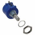
The motors in the heating system in GMCs have a "POT" for feedback. (in this case) they add an extra gear that does 3/4 turn when the valve does 6.5 turns. I have one open on my desk.

You can get POTs with no end stop.
 
Last edited:

GetDeviceInfo

Joined Jun 7, 2009
2,284
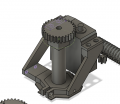
My typical experience in industry is that either drive or driven shaft would drive a threaded nut, which would trip micro switches. The idea of a scroll embedded onto one of the gears is basically the same, on a different plane. Current would be a challenge, as max load will be in breaking away from seal friction, and seating the gate closed. Motor/circuit power will be sized to perform those functions.
 

MisterBill2

Joined Jan 23, 2018
27,980
Unless you already have the gate valves installed, I agree with "Y" that a ball valve is a vastly better choice. Unless the water is mineral laden, and the valve is to only operate rarely. One other thing is that there are also three-way ball valves available. So you could even have a scheme of ONE,the OTHER, and OFF, if that would be any benefit. The beauty is that the same gear reduction scheme can drive a lead-screw to move a lever to operate the ball valve. And a switch for each position would be simple and easy.
 

Thread Starter

Electrodood

Joined Aug 31, 2023
23
Put a small resistor in series with the motor return current to ground and measure the voltage across it with the A/D converter in a micro.
For example a 5Ω resistor would give 0.35V at the 70mA run current, and 3V at the 600mA stall current.
What is the motor operating voltage?

Will you be using a bridge connection to reverse the motor direction?
Yes, I plan on using a bridge and the operating voltage is 12.6 volts maximum and 11.4 minimum. I use three 18650 cells in series.
 

Thread Starter

Electrodood

Joined Aug 31, 2023
23
Thanks to everyone who took the time to pitch in. I'll try to reply to your points here,

Other valves
My application requires 1 inch valves and solenoids get pretty expensive and large at that range.
I use these valves to choose which overhead tank to send water to from a pump.the water has to go up more than 30 feet and it's even fine if the valves are open a few millimetres which I can correct for in code. So no perfect seal is necessary.
Screenshot 2025-01-19 105647.png
Ball valves were part of my original design with a 35kg servo, even with which the Torque needed to open it proved too large. I even tried worm drives at one point but the friction in 3D printed ones along with too much play in the structure made it worse at transferring power than the current solution.

Stalling
Currently the motor is able to recover from a stall on its own. The motor's gearbox in metal and should have 5 or 6 reduction gears. The external gears are 3D printed in PLA plastic.
Iam using a DPDT switch now to control for testing purposes, I'll make a bridge and use a micro to repeatedly open and close the valve with the stall-current feedback solution. I think after some time the jamming behaviour will come to be.
As WBahn said, I could try playing with motor current. Will this work => I'll limit the current to the motor to like 150mA while the stall current that I observed is 600mA. While breaking away from the open or closed positions alone I'll bypass the current limiting circuit.

Too much power draw
As GetDeviceInfo pointed out, the motor stall may steal all the current away from the micro for any operations. But if the solution with limiting the stall current I proposed above works, that would solve this problem too.

Power recovery
To combat power outage, Ill write code so that the micro will always write in the EEPROM what the valve state should be and along with it a homing sequence to recover from power loss.

The reason why iam refraining from mechanical solutions such as a POT is that this is my first time implementing gears and mechanisms outdoor, and though this will for sure have an enclosure, I won't trust my design for mechanical feedback. In my mind, few teeth skipping would be all it takes to render the feedback useless.
But if all else fails, that will be my option.
 

Sensacell

Joined Jun 19, 2012
3,787
Power recovery
To combat power outage, Ill write code so that the micro will always write in the EEPROM what the valve state should be and along with it a homing sequence to recover from power loss.

Sounds like a lot of herky-jerky that would not yield a reliable solution.
What happens when the power fails in the middle of a move?
 

Thread Starter

Electrodood

Joined Aug 31, 2023
23
Sounds like a lot of herky-jerky that would not yield a reliable solution.
What happens when the power fails in the middle of a move?
When the master asks the valve micro to change state, it will first write it in EEPROM. Once the valve is done actuating, it will also write that it has completed actuating in the EEPROM. The startup after power reset will check if the valve was done actuating and if not that would mean that the power must have gone out during actuation, then it will check the EEPROM again for what state the valve should be at, and it will go to that position.
 

Ya’akov

Joined Jan 27, 2019
10,276
Just a point... open loop systems are inherently unreliable. It really does sound like your application needs to close the loop. No matter whet juggling you do with non-volatile memory, without instrumentation you will have no way to know if your belief about the state of the system is accurate.

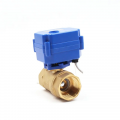
@Sensacell’s suggestion of a 10-turn pot is an excellent one, our you can get something like this, which is pretty damned cheap and includes a limit switch and a motor.

1737280978666.png
 

MisterBill2

Joined Jan 23, 2018
27,980
In some of our projects we used an air cylinder and a lever to quickly open a two inch ball valve. I have no idea if compressed air is available near the TS application area, but that would be worth considering if it is easily available.
But to use the motor and gear train, a lead screw can operate a lever and control a ball valve very well.It can even be a much less expensive one because good accuracy is not required. And limit "microswitches" will provide reliable feedback for many
years.
ALSO, if the pipe installation is not already done, consider the option of a 3-way ball valve. The benefit is only one valve to control.
 
Top