Beginner and need arduino help with SSR and solenoid valve / LEDS are dimmer than expected

Thread Starter

cncduck

Joined Mar 9, 2025
7
So I am making a special curing chamber for 3D printed resins that requires an inert environment. Everything seems to be working but I noticed that the LEDS are pretty dim when running. I have a 12V 3A power supply and I thought I would be in pretty good shape.

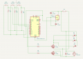
I wired three cherry MX reds (all I had laying around) in a pull down configuration with 10K resistors. Are the cherry MX switches a problem ?

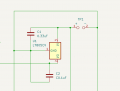
Then I have two buck converters that regulate the LEDS to 11V and the other is 5V to power the arduino.

I have two mosfet modules that turn on a 12V solenoid valve and the LEDs. The leds are rated at 11V @ 1A and I wired them in parallel.

Given the voltage was regulated to 11V, do I need to wire a current limiting resistor to the LEDS ?

Any insight would be super helpful thanks Help.jpg
 

MrChips

Joined Oct 2, 2009
34,625
If you are using 10kΩ resistors in series with a 12 VDC power source, the max current you can ever achieve is 1.2 mA (and lower than that with an LED as the load).

Try reducing the value of the resistor a little bit at a time. Don't go lower than 1kΩ.
 

sghioto

Joined Dec 31, 2017
8,633
I would suspect the 12V 3amp power supply.
The three LEDs are already at 3 amps plus a solenoid , two converter modules and an Arduino.
 

Thread Starter

cncduck

Joined Mar 9, 2025
7
If you are using 10kΩ resistors in series with a 12 VDC power source, the max current you can ever achieve is 1.2 mA (and lower than that with an LED as the load).

Try reducing the value of the resistor a little bit at a time. Don't go lower than 1kΩ.
Ok ! Ill give that a try ! Thanks
 

MisterBill2

Joined Jan 23, 2018
27,159
Welcome to AAC!
For RED LEDs you can use a guess that the required forward voltage is about two volts. Then you can select the forward current to be20 Milliamps, which was quite common for older red LEDs So the series resistor needs to drop ten volts at 20 milliamps. V=I xR, solving for R, =V/I=10/0.020=5 x 100=500 ohms. a 470 OHM resistor will be close enough. Using the 10K resistor demonstrates that an LED will illuminate a bit at a much lower current.
 

sghioto

Joined Dec 31, 2017
8,633
Yeah I even used a 12V 5A power supply and it was behaving the same.
Check the input and output voltages on the 11 volt regulator.
That regulator requires a 12.5 volt input to get 11 volts out but rated 15 watts max which means 1.36 amps at 11 volts.
Three LEDs is too much of a load in IMO.
 
Last edited:

sghioto

Joined Dec 31, 2017
8,633
Using the 10K resistor demonstrates that an LED will illuminate a bit at a much lower current.
There are no red LEDs.
The MX cherry reds are switches not LEDs with a 10K pulldown resistor connected to inputs on the Arduino.
The problem is with the high current LEDs.
 
Last edited:

Thread Starter

cncduck

Joined Mar 9, 2025
7
Thanks @MisterBill2 happy to be here !

@sghioto & @MrChips So it sounds like the buck converter might be the issue so I am just going to remove it and let the LEDS run at a slightly higher voltage for now to see if that changes anything. I have a 12V 5A power supply as well so Ill go ahead and swap it out despite the form factor not being the best just to eliminate any power insecurities. Ill also switch out the pull down resistors to a lower value as well and report back !
 

BobaMosfet

Joined Jul 1, 2009
2,211
To be fair, I think it's your converters. Almost no converter is able to output 3-5A. They thermally shut down due to the sheer wattage you're trying to run through them (could be 27W). Learn how to do the calculations as shown in a datasheet, to determine thermal values, and what you can do to heatsink that heat away.

Instead, use voltage regulators. The only regulator I know of that will do what you want is: LM1084IT-5.0/NOPB-ND
You can get that at DigiKey. Get a couple to play with. It's made by TI, the datasheet is _EXCELLENT_.
 

Attachments

MisterBill2

Joined Jan 23, 2018
27,159
Certainly the power supply capability could be the overall problem.
You should be able to research the current requirements of each of the items you are attempting to power. My guess is that is more than the supply is able to deliver.
 
The IRF520 MOSFET module board, that mosfet is not fully turned on with only 5V gate-drive from the Arduino.
You'd have to check the mosfet part number and see if it is logic-level or not. It's possible they are only partially on and that is why the LED's are dim.
 

Thread Starter

cncduck

Joined Mar 9, 2025
7
Alright so I removed the buck converter running the LEDS at 12V for now. Its the mosfets @prairiemystic and @bertus got it. @sghioto you were correct that the resistors did not make much of a difference. @MisterBill2 I swapped out the power supply to a 12V 5A power supply just to eleminate that variable. I found this guide using the TIP120 mostfet which seems capable of acting as a switch at these loads. I picked up some of them and it seems to be working well ! Thanks everyone for helping me work this out !

During my investigation I decided to just learn some kicad basics because dealing with this rats nest of wires has been brutal honestly and this would just be a great skill to unlock.

Does this schematic look right to yall ? Ideally I would use an L7805CV to provide 5V to the arduino and the buttons. Then run the 12V to the TIP120's / LEDS / solenoid.
 

Attachments

sghioto

Joined Dec 31, 2017
8,633
Diode D4 should be installed like this:
1741839452412.png
Don't see a ground connection from the negative supply to the 7805 pin1.
The TIP120 is a Darlington Transistor not a mosfet for future reference.
 
Top