Facebook
 Google
 GitHub
 Linkedin
I've no real background in electronics, but i'm jumping in the wrong end of the pool and trying to make a milliohm meter.
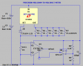
I've been using LTSpice to model the ideas and in this process, trying to understand what's going on. Below is where i'm at and the system is working (according to LTSpice):

However, clearly battery V1 is taking all of the test load and will eventuially discharge at a higher rate.
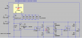
I've been able to get the system to almost work with a single battery, but once the DUT starts getting down around 70mOhm the opamp starts bottoming out and hitting its output offset voltage limit and the output sits up at around 70mV.
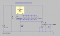
I've looked at a negative rail supply and have modelled an LTC660 to give the op amp a negative supply, but LTSpice really shows a noisy output that's mostly accurate.
Could I ask for some guidance on how I might either get a two-battery system to work or get the op amp -ve supply just low enough to get me to 0V output?
I've been using LTSpice to model the ideas and in this process, trying to understand what's going on. Below is where i'm at and the system is working (according to LTSpice):
However, clearly battery V1 is taking all of the test load and will eventuially discharge at a higher rate.
I've been able to get the system to almost work with a single battery, but once the DUT starts getting down around 70mOhm the opamp starts bottoming out and hitting its output offset voltage limit and the output sits up at around 70mV.
I've looked at a negative rail supply and have modelled an LTC660 to give the op amp a negative supply, but LTSpice really shows a noisy output that's mostly accurate.
Could I ask for some guidance on how I might either get a two-battery system to work or get the op amp -ve supply just low enough to get me to 0V output?