Schematic of a battery-powered audio range sinusoidal oscillator

Thread Starter

RosenDochev

Joined Dec 20, 2025
11
Hello everyone.
Since I am new to your community and do not fully understand the language in which it is written here, I apologize in advance.
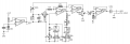
Now on to the main topic, I need a circuit for a sine wave oscillator in the audio range, but I would like it to be unipolar (or battery) powered and of course have the ability to adjust the frequency of the output signal. Also important for me is the circuit not to use the widely used chips like XP2206 or 8038 (I don't like how they work), and the next important part of the project for me is the circuit, if possible, it should be tested, the variant and it doesn't matter whether it will be a twin-T or a Wien bridge or another type, it doesn't matter, I will try everything that I haven't tried yet.
 

wayneh

Joined Sep 9, 2010
18,087
Do you really need to build your own? Every smartphone can run an app to output a sine wave over the entire audio range and then some. Very accurate and precise.
 

Thread Starter

RosenDochev

Joined Dec 20, 2025
11
Do you really need to build your own? Every smartphone can run an app to output a sine wave over the entire audio range and then some. Very accurate and precise.
Thanks for the answer, but yes, I really want a separate circuit, I prefer to use circuits with transistors or operational amplifiers, as separate modules, I am not a fan of sterile modern methods and digital synthesis of these natural waves. In fact, I have many devices that produce such a signal, but they do not sound as soft and lively as transistor circuits, let alone tube circuits, so I want help with a working circuit that someone has tried :)
 

wayneh

Joined Sep 9, 2010
18,087
Well OK but that's a whole bunch of specifications beyond an audible sine wave. You want some specific shaping - error - to achieve "soft and lively".
 

Thread Starter

RosenDochev

Joined Dec 20, 2025
11
Rather, my feeling for the sound of this type of circuit for something more alive comes from the possibility of more control, not least of which are the physical buttons, potentiometers and other control methods, and most of all the analog response, which with the help of encoders, touchscreens and modern devices are too simple to use and do not have the charm that I see in older devices. And modern devices combine more than one function in themselves, and I am a bit old-fashioned and like each device to perform one function. I apologize for the long posts.
 

Thread Starter

RosenDochev

Joined Dec 20, 2025
11
Hello,

Perhaps you can see some circuits here:
https://www.radiolocman.com/shem/schematics.html?di=646217
https://www.radiolocman.com/shem/schematics.html?di=662479

The dual supply could be 2 times a 9 volts battery.

Bertus
The circuits are good, I made a variation of the one from the second link years ago, but with LM324 with slightly different values of the elements, it works with a unipolar power supply and is a relatively good circuit, but LM324 is also slow for this and your suggestion is perhaps better and it is worth experimenting with it, thank you. Regarding the two batteries, yes the method works, I have tried it, it works but I will apologize for my impudence, I do not like it.
 

Thread Starter

RosenDochev

Joined Dec 20, 2025
11
Several schemes are described here. You will need an oscillator with stabilization, for example with LED/LDR

https://sound-au.com/articles/sinewave.htm#s3a

You will need two batteries to power this device
Thank you for your answer, in fact, I was trying to make one of the circuits today, but I didn't have enough time. I've almost assembled all the elements on a breadboard, but I want to try adding a virtual ground with another operational amplifier and see if the circuit will work.

sine-f552.gif
 

MisterBill2

Joined Jan 23, 2018
27,164
I do not think that the "specifications" were at all extreme. Not at all. Making it with discrete components is certainly a way to learn how it actually works. Besides that, in some parts of the world the latest things are not conveniently available at a reasonable price. The TS asked for "sine wave" but did not specify an unreasonable low distortion level. Probably a "twin tee" oscillator will work, and that could be powered from a single 9 volt battery, be low distortion, and have an easily adjustable frequency. And just resistors, capacitors, and a bipolar transistor. The circuit in post #9 could work, it could even use a single LM324 quad opamp, and a single 9 volt battery supply. BUT the power connections are bot shown. AND unfortunately that mythical ground connection has enteredthe picture.
 

hrs

Joined Jun 13, 2014
520
I've built the attached circuit. It works well, from around 20Hz to 40kHz. For through-hole construction the jFET will be hard to find, beware of fakes. For the 21k resistor R206 you could use a standard 22k or from a batch of 20k resistors find one that has a measured resistance more that double the 10k R204.

I've also attached an interesting article, the pdf. I haven't gotten around to this yet so I can't attest to it.
 

Attachments

MisterBill2

Joined Jan 23, 2018
27,164
All of the suggested circuits so far are much more complex than the simple Twin--T circuit, which uses a single opamp. And also the "Bridged -T" and Wien Bridge" single op-amp oscillators , which have many variations, including versions using a single transistor.
There are also simple RC filter oscillators that resemble a three or four section RC high-pass filter, and use either a single transistor or an op-amp as the gain element.
 

sparky 1

Joined Nov 3, 2018
1,218
7 Hertz sinewave has large capacitors for low frequency. The use of a potentiometer useful in audio.
The transistor design is simple. The page includes an ltspice file makes it easy to modify for other frequencies.
The attenuation chart could be useful testing microphones, sound, amplifiers ect.
Low Frequency Oscillator

The author uses ltspice and demonstrates the many parameters of a two-stage audio amplifier.
These are tools that shows more of the whole picture. It has some of the terminology and familiarity that comes with practice.
What stands out to me is how well he uses winscope and linux as well as ltspice.
Audio Preamp
 
Last edited:

AnalogKid

Joined Aug 1, 2013
12,043
In fact, I have many devices that produce such a signal, but they do not sound as soft and lively as transistor circuits, let alone tube circuits,
A true sinewave signal has no harmonics. None. Zero. Thus, any "soft and lively" audible characteristics that you hear are by definition artifacts introduced into the signal by the amplifier and speakers. Nothing you do in the production of a true sinewave, such as go from a Wein circuit to a quadrature circuit to a twin-T circuit to a phase shift or bubba circuit, has any affect on the character of the signal because the signal has no character. Character comes from harmonics and harmonics come from distortion, so Low-distortion versions of those circuits will measure and sound identical because they are identical. If you can hear differences among the circuit types, then the circuits need more work. Don't confuse things that sound different because of noise and distortion with things that sound different because of their core design.

ak
 
Last edited:

Thread Starter

RosenDochev

Joined Dec 20, 2025
11
I've built the attached circuit. It works well, from around 20Hz to 40kHz. For through-hole construction the jFET will be hard to find, beware of fakes. For the 21k resistor R206 you could use a standard 22k or from a batch of 20k resistors find one that has a measured resistance more that double the 10k R204.

I've also attached an interesting article, the pdf. I haven't gotten around to this yet so I can't attest to it.
Thank you for the interesting circuits, I really like the one with the JFET transistor, I will simulate it and then implement it, it really looks interesting and will probably behave stably. In truth, I made the circuits in your PDF file out of curiosity and they work, with good filtering they look and sound almost like a sine wave :), their working principle personally resembles a digital-to-analog converter to me.
 

Thread Starter

RosenDochev

Joined Dec 20, 2025
11
A true sinewave signal has no harmonics. None. Zero. Thus, any "soft and lively" audible characteristics that you hear are by definition artifacts introduced into the signal by the amplifier and speakers. Nothing you do in the production of a true sinewave, such as go from a Wein circuit to a quadrature circuit to a twin-T circuit to a phase shift or bubba circuit, has any affect on the character of the signal. Low-distortion versions of those circuits will measure and sound identical because they are identical. If you can hear differences among the circuit types, then the circuits need more work. Don't confuse things that sound different because of noise and distortion with things that sound different because of their core design.

ak
You know, you are actually very precise and right in your explanation, really after so much time I now think that all that gave me the feeling of a different live signal were the noises and defects in the earlier circuits (from the 70s and 80s) when the transistor started to displace the lamp and the transistors themselves were noisier and more unstable, but each circuit back then required individual adjustment and its own character of operation. Apparently, from those old machines I was left with the impression that I felt without thinking about what it actually was. Thank you, a person really learns all his life.
 

MisterBill2

Joined Jan 23, 2018
27,164
Certainly AK is right!! Of course, it is the harmonics and other distortion that give other instruments their "special character" that defines a particular sound.
Consider some of the incredibly distorted acid-rock from the late sixties, with electric guitars played thru over-driven tube amplifiers with failing output tubes, and other problems as well. They were the inspiration for the FUZZ pedals, when the replacement transistor amplifiers could not produce the distortion the same way.
So pure sine wave sound is great for testing systems and probably a lot of other audio activity.

AND the "character" of the sound comes from the imperfections and distortions.
 

Thread Starter

RosenDochev

Joined Dec 20, 2025
11
Certainly AK is right!! Of course, it is the harmonics and other distortion that give other instruments their "special character" that defines a particular sound.
Consider some of the incredibly distorted acid-rock from the late sixties, with electric guitars played thru over-driven tube amplifiers with failing output tubes, and other problems as well. They were the inspiration for the FUZZ pedals, when the replacement transistor amplifiers could not produce the distortion the same way.
So pure sine wave sound is great for testing systems and probably a lot of other audio activity.

AND the "character" of the sound comes from the imperfections and distortions.
Yes, I absolutely agree with you and the others, I just really hadn't thought about all these things until now. Of course, the idea of the generator I want to build with a suitable circuit remains :)
 

AnalogKid

Joined Aug 1, 2013
12,043
See if you can find any of these - ICL8038

Rejected in post #1.
Also important for me is the circuit not to use the widely used chips like XP2206 or 8038 (I don't like how they work),

Given what the TS is trying to achieve, I agree with him for this application. A multiple-breakpoint sinewave shaper adds high-frequency harmonics to the signal that are clearly audible in a controlled listening environment.

The 8038 (and especially the Maxim variant) is a great part - cheap, reliable, well-understood, excellent application support, decent output amplitude stability, OK waveform distortion for the price, and an insane single-pot adjustment range. It is great for sweeping the frequency response of a guitar amp, but not for this.

ak
 
Last edited:
Top