battery charge indicator

Thread Starter

Viktor Vaughn

Joined Mar 21, 2015
24
Hello everyone,

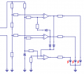
I am working on a battery monitoring ciruit that I am having problems with. My instructor wants me to use a LM339 comparator with a tri-color LED. The circuit will be powered from the 6v battery source it is monitoring.

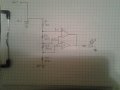
He wants the window voltage to be between 3v-2.5v, I attached his sketch he drew but the way he draws things is unclear and frustrating. so either I am a really dumb student or I am looking too deep into this, but if anyone can give me a clear and better understanding would be appreciated.
 

Attachments

Ramussons

Joined May 3, 2013
1,404
No attachment. Upload the file please.


Ok maybe a delay in upload.


The drawing looks like a "graphical" thinking on the part of the instructor, and a copy of that as such will not work.

You need to have 2 comparators with trigger points at 2.5 Volts and 3.0 Volts.
If you intend to use a Common Cathode Tri Color LED, then Lo = 0 Volts, Hi = 6 Volts

You will have 3 states -
* Both Comparators Low
* 2.5 V Triggered Hi, 3.0 V Low
* Both Comparators Triggered Hi

You can use the 3 states to configure lighting of each colour. Guess you can develop the circuit.
 
Last edited:

Thread Starter

Viktor Vaughn

Joined Mar 21, 2015
24
No attachment. Upload the file please.


Ok maybe a delay in upload.


The drawing looks like a "graphical" thinking on the part of the instructor, and a copy of that as such will not work.

You need to have 2 comparators with trigger points at 2.5 Volts and 3.0 Volts.
If you intend to use a Common Cathode Tri Color LED, then Lo = 0 Volts, Hi = 6 Volts

You will have 3 states -
* Both Comparators Low
* 2.5 V Triggered Hi, 3.0 V Low
* Both Comparators Triggered Hi

You can use the 3 states to configure lighting of each colour. Guess you can develop the circuit.
So I only need to use 2 of the comparators instead of all 4?
 

WBahn

Joined Mar 31, 2012
29,979
What is the interface to this tricolor LED? Is it two pins or three (or four)?

It looks like what the instructor wrote on the board was just snippets in the context of the lecture and, as such, is not complete by itself.

But if you understand the concepts covered up to this point, then you should be able to take a clean sheet of paper and set out the requirements for the project, then break that down into separate tasks, and then implement each task. Take your best shot at that and if you are still having problems report back with your best attempt at a solution.
 

Thread Starter

Viktor Vaughn

Joined Mar 21, 2015
24
What is the interface to this tricolor LED? Is it two pins or three (or four)?

It looks like what the instructor wrote on the board was just snippets in the context of the lecture and, as such, is not complete by itself.

But if you understand the concepts covered up to this point, then you should be able to take a clean sheet of paper and set out the requirements for the project, then break that down into separate tasks, and then implement each task. Take your best shot at that and if you are still having problems report back with your best attempt at a solution.
I will, thank you.
 

Thread Starter

Viktor Vaughn

Joined Mar 21, 2015
24
[QUOT="Viktor Vaughn, post: 848272, member: 263785"]I will, thank you.[/QUOTE]
This is my attempt to solve this problem, please forgive me if I missed something that is so simple. It's just that I have been working on this for a while and I am burned out and frustrated.

I really want to be a good engineer, but when I run into to problems that I can't understand, I feel ashamed and discouraged. I would appreciate any knowledge you can give me sir.
 

Attachments

Ramussons

Joined May 3, 2013
1,404
Victor, how good are you in understanding Circuits? It's not our intention to ridicule you in any way.

Now, in the file that you have attached, you will note that the Comparators get their inputs from a 3 Volt Zener supply. That voltage is NOT going to change. R1, R2, R3 and R4 form a voltage divider AND the voltage being divided is that Fixed Zener Voltage. So what are we monitoring?

For monitoring the Battery Voltage, we need to compare it against a Reference - normally a Zener Voltage. Now think of how to redraw your circuit so as to have a Reference Voltage on one input of your comparator and the Battery Voltage, or a fraction of it on the other input.

That will be a starting point. More as we go along.
 

MrAl

Joined Jun 17, 2014
11,389
Hi,

I agree that one input to the comparator has to be at a fixed voltage and the other has to monitor the actual battery voltage. That way the comparator trips for some voltages and not others.

Maybe you should start with one comparator, just make it trip at a certain voltage like 2.5v, then we can go from there to get the 'window' comparator going.

If you are using a two lead bi color LED then you have to power it with a reverse current to get the other color to light up, and that reverse current means you have to have a reverse voltage. This could be done by 'biasing' one lead of the LED with two resistors that form a voltage divider. Then when the other lead of the LED goes low one color lights up, and when the other lead goes high the previous color lights up.
For now though maybe you should concentrate on just lighting one single color LED.

The multi lead LEDs are easy to use because each LED inside has its own anode or cathode. To light a specific color you just power the appropriate lead and dont power the other leads. These typically come in tri color versions so you actually get three individual colors to work with, usually Red, Blue, and Green.
 

MikeML

Joined Oct 2, 2009
5,444
Viktor,

Ask your instructor and yourself this question:

"Under what conditions does the voltage of a battery indicate its state-of-charge?"

If you research this, you (and your instructor) may be surprised.

Your comparator circuit is nothing but a voltmeter, and a low-resolution, likely not very precise one, at that.
 

frpr666

Joined Feb 2, 2010
50
Hi,
To solve your problem you have to know
1/ how the comparator works
2/ how the resistor divider works
please look at this picture:
http://forum.allaboutcircuits.com/attachments/150409-png.83728/
1/ U1 is TL431 which is like as a zener diode. It provides fixed volage 2.85V
2/ (R8+R9)&R10 is the resistor divider. It provides fixed volage 1.5V
3/ R1&R2 is another resistor divider. It provides input voltage x 0.5. It means:
For 3V Vin you will get 1.5V at R2
For 5.7V Vin you will get 2.85V at R2
4/ U2B, if the Vin < 5.7V, then U2B is high and the LED1 shine.
5/ U2A, if the Vin > 3V, then U2A is high and the LED2 shine.
6/ For Vin 0..6V, you will get:
0..3V, LED1
3V..5.7V, LED1 & LED2 both
5.7V..6V, LED2
7/ the comparator LM339 doesn't have push-pull output. You have to connect and an resistor between the U2A output and V=6V. The same goes for U2B.
 

Thread Starter

Viktor Vaughn

Joined Mar 21, 2015
24
Hi,
To solve your problem you have to know
1/ how the comparator works
2/ how the resistor divider works
please look at this picture:
http://forum.allaboutcircuits.com/attachments/150409-png.83728/
1/ U1 is TL431 which is like as a zener diode. It provides fixed volage 2.85V
2/ (R8+R9)&R10 is the resistor divider. It provides fixed volage 1.5V
3/ R1&R2 is another resistor divider. It provides input voltage x 0.5. It means:
For 3V Vin you will get 1.5V at R2
For 5.7V Vin you will get 2.85V at R2
4/ U2B, if the Vin < 5.7V, then U2B is high and the LED1 shine.
5/ U2A, if the Vin > 3V, then U2A is high and the LED2 shine.
6/ For Vin 0..6V, you will get:
0..3V, LED1
3V..5.7V, LED1 & LED2 both
5.7V..6V, LED2
7/ the comparator LM339 doesn't have push-pull output. You have to connect and an resistor between the U2A output and V=6V. The same goes for U2B.
Are (R3, R4,&R7) and the 2.5v irrelevant?
 

frpr666

Joined Feb 2, 2010
50
You can disconnect: R4&R7&TL431 and connect a zener diode instead. R3 will feed the zener diode. The TL431 is like adjustable zener diode but more accurate. The R4 and R7 is just another resistor divider.
 

WBahn

Joined Mar 31, 2012
29,979
Viktor,

Ask your instructor and yourself this question:

"Under what conditions does the voltage of a battery indicate its state-of-charge?"

If you research this, you (and your instructor) may be surprised.

Your comparator circuit is nothing but a voltmeter, and a low-resolution, likely not very precise one, at that.
It's almost certainly an exercise that is meant to focus on making a three-zone comparator and the whole set of words having to do with state of charge is just mumbo-jumbo trying to make it sound like a "real" problem. Like you, I wish that "real" problems were thought through much better so that they actually had some relation to reality (and, to be fair, sometimes the simplifying assumptions -- and the degree to which they are reasonable -- are discussed when the problem is given). But given that most instructors and most text book authors have little to no industry experience, expecting that would be quite unrealistic.
 

Thread Starter

Viktor Vaughn

Joined Mar 21, 2015
24
You can disconnect: R4&R7&TL431 and connect a zener diode instead. R3 will feed the zener diode. The TL431 is like adjustable zener diode but more accurate. The R4 and R7 is just another resistor divider.
It's almost certainly an exercise that is meant to focus on making a three-zone comparator and the whole set of words having to do with state of charge is just mumbo-jumbo trying to make it sound like a "real" problem. Like you, I wish that "real" problems were thought through much better so that they actually had some relation to reality (and, to be fair, sometimes the simplifying assumptions -- and the degree to which they are reasonable -- are discussed when the problem is given). But given that most instructors and most text book authors have little to no industry experience, expecting that would be quite
It's almost certainly an exercise that is meant to focus on making a three-zone comparator and the whole set of words having to do with state of charge is just mumbo-jumbo trying to make it sound like a "real" problem. Like you, I wish that "real" problems were thought through much better so that they actually had some relation to reality (and, to be fair, sometimes the simplifying assumptions -- and the degree to which they are reasonable -- are discussed when the problem is given). But given that most instructors and most text book authors have little to no industry experience, expecting that would be quite unrealistic.
Thank you for your words of wisdom and encouragement.
 

Thread Starter

Viktor Vaughn

Joined Mar 21, 2015
24
You can disconnect: R4&R7&TL431 and connect a zener diode instead. R3 will feed the zener diode. The TL431 is like adjustable zener diode but more accurate. The R4 and R7 is just another resistor divider.
Thanks for sharing your knowledge, unlike my instructor I can understand your teaching.
 
Top