 Facebook
 Google
 GitHub
 Linkedin
Hi,
I just got a bit interested in radio design, very basic few-transitor type and I have some questions regarding the basic concepts I would like to ask:
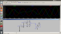
1. I have been reading about superhet receivers and I believe I understood the basic concept behind one, what bugs me is the hardware solution to concept of mixer and its link to audio mixers, also the term of mixing signals. If I understood correctly audio mixer should add signals in time domain producing only two original signals when observed in frequency domain, while the standard RF mixer should produce original signals plus the sum and difference of the signals. Now the question is : how is audio mixing different from RF mixing from point of circuit design ? Trying to simulate a basic audio mixer circuit which should simply "add" voltages I can see that a 100 Hz (difference of 1k and 900Hz) envelope is present which is clearly not the point of audio mixer. Also by searching the internet for audio mixers and RF mixers I could not see any general difference behind the two circuits: both can be accomplished by driving multiple signals to BJT base ( 2 audio signals in audio mixers and RF signal + local oscilator for RF mixers). Only obvious difference is the frequency of the input signals but that should not be of any importance for the basic design of the circuit?
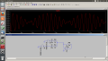
2. From my intuitive point of view, any signal "adding" should produce a "new" signal if we assume that AC signal can be frozen in any time and observed as DC signal, so the resulting signal would be (V1+V2)/2 if the circuit is like the one on the picture (green-op amp output, red and blue - signal generators).
I seem to be missing something here so I was hoping for some explanation. Thank you in advance.
Also I would be very gratefull if you could point me to some literature regarding design of radio circuits which includes explanation of building blocks, I cant seem to find any on the internet, mostly bare schematics.
I just got a bit interested in radio design, very basic few-transitor type and I have some questions regarding the basic concepts I would like to ask:
1. I have been reading about superhet receivers and I believe I understood the basic concept behind one, what bugs me is the hardware solution to concept of mixer and its link to audio mixers, also the term of mixing signals. If I understood correctly audio mixer should add signals in time domain producing only two original signals when observed in frequency domain, while the standard RF mixer should produce original signals plus the sum and difference of the signals. Now the question is : how is audio mixing different from RF mixing from point of circuit design ? Trying to simulate a basic audio mixer circuit which should simply "add" voltages I can see that a 100 Hz (difference of 1k and 900Hz) envelope is present which is clearly not the point of audio mixer. Also by searching the internet for audio mixers and RF mixers I could not see any general difference behind the two circuits: both can be accomplished by driving multiple signals to BJT base ( 2 audio signals in audio mixers and RF signal + local oscilator for RF mixers). Only obvious difference is the frequency of the input signals but that should not be of any importance for the basic design of the circuit?
2. From my intuitive point of view, any signal "adding" should produce a "new" signal if we assume that AC signal can be frozen in any time and observed as DC signal, so the resulting signal would be (V1+V2)/2 if the circuit is like the one on the picture (green-op amp output, red and blue - signal generators).
I seem to be missing something here so I was hoping for some explanation. Thank you in advance.
Also I would be very gratefull if you could point me to some literature regarding design of radio circuits which includes explanation of building blocks, I cant seem to find any on the internet, mostly bare schematics.
Attachments
-
 353.2 KB Views: 12
 -
 402.4 KB Views: 12


