Basic Fixed Resistor with Potentionmeter Question

Thread Starter

soma56

Joined Nov 11, 2018
12
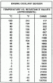
Please excuse my noob question as I'm very new to electronics and circuitry. I'm attempting a mod on a diesel vehicle to which I need to add resistance to a specific wire. I'd like to be able to adjust the ohms on that wire anywhere from zero to 2.2k ohms. In one instance (as seen in the image below) the author suggested having a variable resistor potentionmeter as a means of adjusting the ohm's in addition to a fixed resistor. My questions are as follows:

If I have a fixed resistance of 2.2k ohms in addition to variable resistor potentionmeter would the total resistance be 2.2k ohms in addition to whatever setting I place on the variable resistor potentionemeter?

(Assuming the above is correct) Would it not be better to implement a variable resistor potentionemeter and install it without a fixed resistor (contrary to the image) and use it to set my desired resistance/setting?

Finally, I'm assuming the supply wire would go to the 'center' prong? (it's not clear in the diagram/image).

Thank you in advanced for any insight and (again) please excuse my novice questions.


Reloadron

Joined Jan 15, 2015
7,523
If I have a fixed resistance of 2.2k ohms in addition to variable resistor potentionmeter would the total resistance be 2.2k ohms in addition to whatever setting I place on the variable resistor potentionemeter?
Yes

(Assuming the above is correct) Would it not be better to implement a variable resistor potentionemeter and install it without a fixed resistor (contrary to the image) and use it to set my desired resistance/setting?
No but it can depend on the application. In this case it looks like the resistances are being used to replace a signal fro the IAT sensor which I see as Intake Air Temperature. So what exactly is your goal here? Also they reference 220 Ohm fixed and 10 K pot. I would used the fixed resistor as I am not sure how the ECU reads the IAT sensor.

Ron
 

Reloadron

Joined Jan 15, 2015
7,523
Typical IAT sensor resistance chart. Note they are NTC (Negative Temperature Coefficient) meaning as temperature decreases the resistance increases. I assume your objective is to remove the IAT and replace it with a pot?

IAT Sensor Chart.gif

Ron
 

Thread Starter

soma56

Joined Nov 11, 2018
12
Thanks Ron. The application or goal is slightly different then the author although the same in principal. I'm adjusting the resistance on the fuel temperature sensor which can be anywhere from 100ohms to 2.2k ohms.

The main goal is to convert a newer diesel engine to run off used vegetable oil. I've converted and ran older diesels off of used veg for years and know a lot about the process. A 'newer' diesel I'm working on is a little more finicky. The fuel temperature wire is communicated to the ECU and adjusts the timing of when the fuel is introduced into the engine accordingly. Because waste veg oil has a higher viscosity then diesel (even when heated) this mod is a way to trick the ECU into thinking the fuel is much colder thus advancing the timing of the engine to allow for a better and more complete combustion.

With my specific engine I've heard varying opinions on how many ohm's to set the resistance at hence my desire to adjust it thereby finding that sweet spot based on performance, idling rpm, etc.

I'm confident a 200ohm resistor will have little impact. With that said should I implement a 200 (or 220 as per the diagram) ohm fixed resistor in addition to a variable resistor potentionmeter to achieve my goal? A 10k ohm resistor would be overkill and (I suspect) a little more difficult to fine tune. Do variable resistor porentionmeters come in smaller ranges (for example 0 to 2.5kohms)?

I assume your objective is to remove the IAT and replace it with a pot?

My apologies, I posted my response before reading your second reply. That's not the objective as noted above.
 

MrChips

Joined Oct 2, 2009
30,824
Sure you can use a single variable resistance and eliminate the fixed one. However, it is a question of range and sensitivity. It is a toss up between course control vs fine control.

If you have a single 10KΩ pot, your range and control is 0 to 10K, or 0-100%. This can be a bad thing for two reasons.

If you have a 100Ω fixed resistor and a 10KΩ pot, your minimum resistance is 100Ω. Your range is now 100Ω to 10.1KΩ i.e. 1 to 100%. This may be advantageous for safety reasons, i.e. you are not creating a dead short which would burn out your pot.

If you have a 1KΩ fixed resistor and a 1KΩ pot, your range is 1KΩ to 2KΩ, or 50% to 100%. You now have finer control.

Typically, you want the pot to nominally be at the halfway position. Hence your overall nominal resistance is 1500Ω ± 500Ω, i.e. ±33%.
The objective is to increase the value of the fixed resistor and decrease the value of the variable resistor to give the finest control while still being able to cover the full range of desirable coverage.
 

Thread Starter

soma56

Joined Nov 11, 2018
12
Re: Ron
Pursuant to your last image the ideal veg oil temperature would be around 176 degrees F. This gives us an approximate existing resistance of 332ohms. Am I correct in thinking that if I add a 2.2kohm resistor that I can trick the ECU into thinking the fuel temperature is that of closer to 86 degrees F at 2532 ohms? The rationality with adding a variable resistor potentionmeter is to allow me to adjust the resistance based on an EGT sensor that I'll be installing to check for how well the engine is combusting the fuel. This is because maybe a 90 odd degree difference in temperature is not enough or perhaps too much...

Re: MrChps
It is a toss up between course control vs fine control...If you have a 1KΩ fixed resistor and a 1KΩ pot, your range is 1KΩ to 2KΩ, or 50% to 100%. You now have finer control...The objective is to increase the value of the fixed resistor and decrease the value of the variable resistor to give the finest control while still being able to cover the full range of desirable coverage.


That makes so much sense – thank you for sharing. So I guess the question I have to determine myself is what half way point in temperature do I wish to establish thus determining what size fixed resistor and pot I use for this system.
 

Reloadron

Joined Jan 15, 2015
7,523
Re: Ron
Pursuant to your last image the ideal veg oil temperature would be around 176 degrees F. This gives us an approximate existing resistance of 332ohms. Am I correct in thinking that if I add a 2.2kohm resistor that I can trick the ECU into thinking the fuel temperature is that of closer to 86 degrees F at 2532 ohms? The rationality with adding a variable resistor potentionmeter is to allow me to adjust the resistance based on an EGT sensor that I'll be installing to check for how well the engine is combusting the fuel. This is because maybe a 90 odd degree difference in temperature is not enough or perhaps too much...
The chart I posted was resistances typical of an IAT (Intake Air Sensor) sensor not a fuel sensor temperature scale. All I am seeing for fuel temperature is:
  1. At 68°F, resistance should be 2.3-2.7 kohms.
  2. At 122°F, resistance should be 0.79-0.90 kohms.
My guess is they are using a thermistor as a sensor with a negative temperature coefficient. The problem is that the numbers I found don't fit into any common thermistor temperature curve but if your picture (drawing) is correct then likely a 5K pot would work or I would just use a 10K pot and 220 Ohm fixed resistor as drawn.

Ron
 

Thread Starter

soma56

Joined Nov 11, 2018
12
Thanks Ron. The consensus I reviewed online (through very few sources as this is a very specific instance) seemed to be that of simply implementing a 2.2k ohm resistor and be done with it. Mind you, this is applied to slightly different engines in addition to my own. I suspect I'm being a tad over-cautious. My approach was to measure the performance on diesel fuel, in addition to having a benchmark with an EGT gauge (on diesel), where I can then not only discover the correct or most efficient combustion temperature but also zero-in the appropriate amount of resistance needed (and adjust accordingly to match the benchmark and performance).

The picture (I initially posted) isn't necessarily correct/accurate and for a different part of the system (air flow) and it was generic in nature albeit the same concept hence my motivation for posting it. With all that said the chart you initially posted is actually consistent/identical with that of coolant fluid that I found. There must be one for diesel somewhere and, yes, I'm pretty confident at this point it's negative temperature coefficient as you suggested.

In spite of everything I think my logic moving forward would be to implement a 1k fixed resistor with a 10k pot based on my research thus far.

I think I owe you and MrChips a big thank you at this point. You've helped clear up a few things. So thank you!
 

DNA Robotics

Joined Jun 13, 2014
650
Do you have an OBD scan tool. If so, does it tell you fuel temperature or resistance of the temp sender. That might help you calibrate it.
 

Thread Starter

soma56

Joined Nov 11, 2018
12
Thanks for the input DNA Robotics. I do but in addition to that I'm ordering a special cable that will allow me to run some special software to not only read everything but also manipulate the ECU. Details: http://www.ross-tech.com/vag-com/. Nevertheless good thinking.

And alas now I'm a little confused having re-read everything...

Ron:
The chart I posted was resistances typical of an IAT (Intake Air Sensor) sensor not a fuel sensor temperature scale. All I am seeing for fuel temperature is:

  1. At 68°F, resistance should be 2.3-2.7 kohms.
  2. At 122°F, resistance should be 0.79-0.90 kohms.
However, I found a chart with the exact same numbers for coolant as per your IAT chart (attached). The ideal chart would be something to reflect the temperature scale of diesel for my purposes, yet, considering the lack of differences between coolant and air - how could these diagrams be identical?

As per Ron's comment on resistance values at specific temperatures (I.E. At 68°F, resistance should be 2.3-2.7 kohms.) I would think this is irrelevant in some respects where any such current resistance exists as I'm simply intending to add a value upon the existing resistance. A chart displaying the specific resistances of diesel fuel temperature to ohms (I'm guessing) is what I'm looking for although, the noob in me is pondering if this is something unique?

Please excuse the following noob question:

With the lack of a diesel temperature chart set aside and following Ron's response will a 68°F temperature diesel fuel consistently produce a resistance of 2.3-2.7k ohms with no outside factors? I guess what I'm attempting to understand is if this a ubiquitous value/range.

I'm no electrical expert but I would think, assuming the above is correct, a chart to compare diesel temperature to an approximate ohm resistance would be readily available to some degree, somewhere online? Am I correct in my thinking or am I way off? And if I'm correct why in blazes would coolant fluid measure the same values as air for ohm resistances?
 

Attachments

Last edited:

ebeowulf17

Joined Aug 12, 2014
3,307
I'm no electrical expert but I would think, assuming the above is correct, a chart to compare diesel temperature to an approximate ohm resistance would be readily available to some degree, somewhere online? Am I correct in my thinking or am I way off? And if I'm correct why in blazes would coolant fluid measure the same values as air for ohm resistances?
None of the sensors in question know or care what material they're measuring the temperature of - they just have a predictable temperature-resistance curve. For any given sensor temperature, they'll have a certain resistance value.

If multiple systems have the same curve, it's because they're using the same type of sensor. If one of them has a different curve, it's because manufacturers are using a different type of sensor there, not because the substance being measured in any way impacts the resistance.

So, there's nothing strange about coolant and air sensors having the same temperature-resistance curves.
 

Thread Starter

soma56

Joined Nov 11, 2018
12
Alas, I'll humbly showcase my lack of electrical skills/knowledge with my logic of it thus far through the diagram below. Questions:

With the switch toggled left (as per the diagram which currently shows right) would this bypass any resistance I have in place (essentially skipping anything/everything I have in place)? The reasoning is that I wish to have the default/original setup for the system when running on diesel.

In the bottom left of the diagram would I simply splice in the wire as shown to connect back in?

With the current wiring set-up for the pot would this allow for more resistance if turned clockwise?


MrChips

Joined Oct 2, 2009
30,824
Almost correct.

All toggle switches do not behave the same way depending on how the switch is mechanically designed.
Normally, when the switch is in the left position, the center and right connections are bridged.

You can check with a conductivity test to be certain.
 

Thread Starter

soma56

Joined Nov 11, 2018
12
All toggle switches do not behave the same way depending on how the switch is mechanically designed...
Thanks for the quick reply. I understand there are many differences between switches. For my purposes, which is to have continuity with the main wire on two potential settings by either (A: leaving it in a default position or B: adding resistance), does my choice of an on/on SPDT switch make sense or is there a better option?
 

ebeowulf17

Joined Aug 12, 2014
3,307
Thanks gentlemen!

If anyone else has any additional insight please feel free to share.
I agree with MrChips that you'll need to confirm the correct pin out for the switch (and for the pot too,) because they aren't totally standardized.

As long as you've got that right, the basic concept definitely looks right to me.
 
Top