Facebook
 Google
 GitHub
 Linkedin
Hello all,
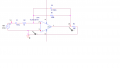
I have a simple task here but I am a little bit confused about amplifier characteristics when saying input impedance @1kHz 1Kohm,
Is it saying simply input of 1KHz signal with signal generator input impedance at 1Kohm?
TY
Saviour
I have a simple task here but I am a little bit confused about amplifier characteristics when saying input impedance @1kHz 1Kohm,
Is it saying simply input of 1KHz signal with signal generator input impedance at 1Kohm?
TY
Saviour
Attachments
-
 664.6 KB Views: 12