Back emf protection across a 24 VAC coil

ebeowulf17

Joined Aug 12, 2014
3,307
Thank you for the advice MB2, the "relay board" is one those $12 relay boards with the 8 relays inline. Each relay has an opto isolator between the relay coil and the input pin connected to the webcontrol board. Also, if I remove the power to the valve coils -- to just allow the relays to pick up and to release normally, there is no problem. As soon as I apply the 24 VAC to allow the valves to pickup, the webcontrol board intermittently goes nuts.

And prior to connecting the weather stuff to the webcontrol board, I had no problems. That was using just the one transformer to power the whole thing. While I could very well be overlooking something, it seems the collapsing fields are radiating noise into the wiring to the webcontrol boards inputs. While I have a hard time believing that, I don't know of another explanation.

I need to disconnect all the weather stuff for a test to ensure all is still well with it disconnected. Although I have changed nothing else in the last several months.
I had a similar problem a few years ago with motors switched via mechanical relays that were messing up serial communication lines. We tried every conceivable means of isolating things and testing components separately, and ultimately determined with a fairly high degree of confidence that arcing across the contacts of the relays was radiating noise out all over the place. Moving the relay away from the sensitive electronics worked, but wasn't practical as a long term solution, only a test.

In our case a snubber in parallel with the load (not across the contacts) was very effective. Having said that, it eliminated 95-99% of the problems, but not all of them, so about a year later we started using SSRs instead of mechanical relays. The SSRs have been incredibly effective.
 

MisterBill2

Joined Jan 23, 2018
27,905
Also MB2, I still can't picture the two diodes back to back with one of the two across the coil. I know I am misunderstanding the explanation. I don't know where each diode is wired into the circuit.
Sorry about the inadequate description. The two diodes would be connected, back-to-back, across the connections where otherwise the solenoid or relay coil would have been connected. So with the voltage applied no current would flow because of being blocked by the diodes. Then, the coil is connected in parallel with one of those two diodes. Now current will flow through the remaining diode and through the coil. When the other half cycle arrives, that remaining diode will block the current, but the coil current will now flow through the diode connected across the coil. So the result is that the current through the coil never reverses, and never cuts off, and so there is no big voltage spike generated. It is a cheap trick but it works well.
 

MisterBill2

Joined Jan 23, 2018
27,905
In what way?

ak
The circuit is simple, a total of three devices, and so detailed a description of the operation that my friend's cat understands it. Of course, it is a quite smart cat.
Perhaps one of the folks who has drawing software can produce a drawing of it, as they have done for me in the past.
 

Thread Starter

frankpc

Joined Jul 25, 2010
41
The two diodes would be connected, back-to-back, across the connections where otherwise the solenoid or relay coil would have been connected.
Thank you MB2. I get it. I appreciate your explaining the theory behind the configuration.

I just found out that the TVS used across the valve coils in the "Open Sprinkler" product is a Littelfuse SMBJ43CA. It appears an axial equivalent is P6KE51CA. Both are priced around 30 cents +/- depending upon quantity. (Plus $8 to ship 10 of them from Mouser).
 

Thread Starter

frankpc

Joined Jul 25, 2010
41
Do you folks have any advice regarding which oscilloscope would be practical to observe the spikes in question here? For example, there is a Rigol DS1102E 100MHz dual trace scope for $300. All I have now is an old B&K analog scope that wouldn't work for something like this.
 

AnalogKid

Joined Aug 1, 2013
12,223
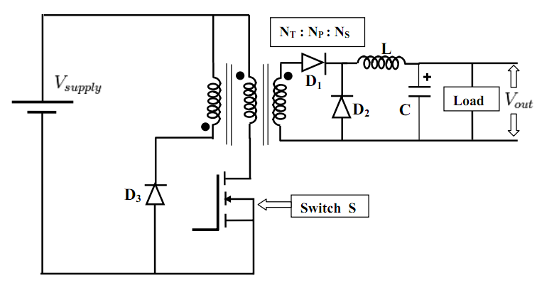
Just that the diagram you linked to seems rather simple, but it is complicated to figure out.
The caption is clear that this is a reduced schematic, but it has the three main elements - a switch transistor (driven by PWM circuit, voltage regulation feedback from the output, etc.), a way to reset the transformer core (the upside down winding and D3), and the output circuit. Feedback and PWM are common to many switching topologies, and are left out for clarity.

In a forward converter, the transformer primary winding and core are charged up through Q1 (the main switch) on what we'll call the first half-cycle of the driving waveform. During this time, the voltage polarity of the primary and the secondary are the same (as indicated by the dots), and secondary current flows through D1, L, and the load. When Q1 turns off for the second half-cycle, the primary winding field collapses, and the voltage across the primary reverses. This means the voltage across the secondary reverses, reverse-biasing D1, so the secondary no longer has a current path and energy in the core cannot go out through the load. That magnetic charge has to go somewhere before the switch turns on again or the core will build up residual charge with each cycle until it saturates. This is what the third winding and D1 fix. When the primary reverses, this drives the dotted end of the third winding down below what we'll call GND (the source end of Q1), turning on D3 and conducting current through the winding, discharging the core. There are other ways to "reset the core", but the third winding technique is very common, especially for higher-power designs.

During the second half cycle, D1 is reverse-biased. When it turns off, the field in L collapses, reversing the voltage across it. This forward-biases D2, so the energy stored in L is delivered to the load. This is why a forward converter is preferred over a flyback design for higher powers - the output inductor is "on" for both half-cycles, first charging up and passing current to the load, then discharging into the load. Compared to a flyback circuit of the same output power, the forward circuit output inductor, rectifiers, and output filter capacitors can be smaller because the peak current is not as much greater than the average current.

ak
 
Last edited:

AnalogKid

Joined Aug 1, 2013
12,223
All I have now is an old B&K analog scope that wouldn't work for something like this.
No automatic reason why not. Specs: age, bandwidth, etc? If the issue is capturing a transient, then maybe you can see what you need to if you stare at the screen with the trigger in normal mode, and let your retina capture the image long enough to see the peak. Old school.

ak
 
Last edited:

Thread Starter

frankpc

Joined Jul 25, 2010
41
Thank you ak for the explanation on the forward converter. I read it twice and plan to read it a couple more times.

Problem with my dual trace B&K, is that its bw initially wasn't high. And the beam itself has dimmed and is not a sharp as it once was perhaps 25 years ago or so. I've had lots of occasions where I would have liked to have had a storage scope and figure perhaps now is the time since I plan to find a solution to this elusive spike issue. Problem is, I have never used a storage scope and I haven't heard of the brands of the reasonably priced scopes offered today. Also not sure what BW is required, but I imagine 50 mHz would be more than enough, but a 100 mHz doesn't cost much more.

Frank
 

Thread Starter

frankpc

Joined Jul 25, 2010
41
Something to keep in mind:

All test equipment lies, but nothing lies like a digital scope.

ak
Actually... it occurs to me that I had made the assumption that a digital scope would be the right thing to do. Would an analog scope be a better idea? I've only used a couple of older analog scopes that were given to me. At work we use techtronix, but I don't want to spend that much for my personal use.
 

MisterBill2

Joined Jan 23, 2018
27,905
That old B&K scope is probably able to display the transient but not as accurately as a far more expensive one would. You can even get a hint of it by connecting a small neon bulb across the coil. Those bulbs trigger at about 65 volts and so that would let you know that the spike was real. Also, you can reduce the spikes just by putting a 24 volt indicator light across the valve solenoid coil. The bulb will light when the valve is powered and flash a bit at shutoff. One more option.
 

Thread Starter

frankpc

Joined Jul 25, 2010
41
That old B&K scope is probably able to display the transient but not as accurately as a far more expensive one would. You can even get a hint of it by connecting a small neon bulb across the coil. Those bulbs trigger at about 65 volts and so that would let you know that the spike was real. Also, you can reduce the spikes just by putting a 24 volt indicator light across the valve solenoid coil. The bulb will light when the valve is powered and flash a bit at shutoff. One more option.
Interesting! Reminds me of the old NE2 days. I had one in my homemade tube-filament checker.
 

David1961

Joined May 28, 2021
1
What type of device should I place across the sprinkler valves to kill the back emf?

would it be unreasonable to expect a small RC snubber circuit , e.g. 1mf & 120 ohm, to work. Or perhaps some sort of TVS diode or varistor?

Thank you.
I realize this is an old post but I was wondering what you finally used to solve your problem. I have sort of the same problem but I'm using five 24VAC solenoids to automate draining my air compressor and air dryer unit. Using an Arduino with some simple code and probably an 8 channel relay board like yours I would assume. It just opens one solenoid at a time for about 1 second. On the bench without the solenoids connected it worked fine. Now that it's in place I have random issues. Sometime it acts like it is ignoring my delay statements, or locks up on a delay statement or totally misses firing a solenoid.

Saw you mentioned the P6KE51CA in a previous post and was wondering if you used that and did it work. Also if it did work was it placed across the contacts or solenoid coil.

Thanks
David
 
Top