B&K 501A Xstr Tester W/ Digital O'scope

tautech

Joined Oct 8, 2019
504
Some comments:
Notice you are in 10 Bit mode, probably not necessary for this.
Notice you have BW limits engaged on both channels, probably not required.
Do you really need a A/div setting for Ch2 ?

Now you have it sorted for the X Plus, try out similar setting with your old 1000 series with much less horsepower which I think will still do curve tracing just fine.
 

Thread Starter

SamR

Joined Mar 19, 2019
5,513
Notice you are in 10 Bit mode, probably not necessary for this.
Notice you have BW limits engaged on both channels, probably not required.
Do you really need a A/div setting for Ch2 ?
Nope, in fact for speed I usually use 8bit. The BW limits are default? or from something else I was doing. Didn't notice an A/div setting. Vert is set for .2V/div and Hor for 1V/div. Which while recommended in their calibration procedure is really arbitrary. Bit of a leftover from the days of having to use the graticule to make measurements. Yup the old scope will work fine for this IF it also inverts, can't remember. Still plenty to learn about this new curve tracer.
 

tautech

Joined Oct 8, 2019
504
The BW limits are default? or from something else I was doing.
Something else you did. Default BW limit displays Full.
However with these new scopes you can set your own preferred Default settings for the scope.
This feature is in the Save/Recall menu and easy to apply or return to Factory default however I recommend you apply the Factory default before making your own settings and then saving them.
Start another thread if you wish to explore these features and I'll walk you through some of them.

Didn't notice an A/div setting. Vert is set for .2V/div and Hor for 1V/div. Which while recommended in their calibration procedure is really arbitrary. Bit of a leftover from the days of having to use the graticule to make measurements.
LOL. You are just as I see me a few years back looking for scales on V/div and timebase knobs where now everything about the way the scope is set is plain and clear on the display in the various settings tabs.
The only way I found to break that habit came from a recommendation from my scope mentor to mentally work out what the scope should display with the settings applied before even connecting it !
 

Thread Starter

SamR

Joined Mar 19, 2019
5,513
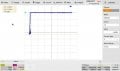
Continuing on with why I started this project, a 6.2V Zener. And according to this test a 6.22V Zener. However, I am feeding in a Sweep Voltage of 20V but only seeing ~1.6V across the Zener?
SDS2104X Plus_PNG_103.jpg
SDS2104X Plus_PNG_104.jpg
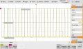
And switching to YT mode to see what is happening.

Even turning the Sweep Voltage to max 100V momentarily I only see 0.817V on the Vertical trace. Am I wrong in thinking that the vertical voltage should follow the sweep voltage? Or is what I am seeing in the vertical trace is simply the change from the voltage applied to the horizontal?

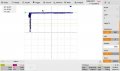
I changed the vertical to 5V/div after discovering that by switching the Vertical Sensitivity on the tester a momentary line appears extending the vertical trace. So, by putting the screen persistence into the infinite mode I can capture it. However, it is only ~15V.
SDS2104X Plus_PNG_105.jpg
Looks pretty ugly printed, much better on the scope.
 

MrChips

Joined Oct 2, 2009
34,982
An I-V curve tracer should be showing I on the vertical axis and V on the horizontal axis.
You need to work out the conversion from grid divisions to current.

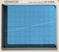
A quick and simple test is to use resistors as your DUT. Try diferent values of resistors, e.g. 100Ω and 1000Ω. The I-V curve should be a straight line passing through the X-Y origin. Knowing the value of the resistor you can work out the current scale.

https://forum.allaboutcircuits.com/threads/diy-i-v-curve-tracer.184368/

1000-ohm resistor
1656953365815.png

Y-scale is 5mA/DIV
X-scale is 1V/DIV
 

Thread Starter

SamR

Joined Mar 19, 2019
5,513
It is a whole lot different than my DCA75 but it stops at 12V and I needed to test a bit higher... Ah well, it keeps me busy.
 

Thread Starter

SamR

Joined Mar 19, 2019
5,513
Tester is not even getting to a 40V pulse and is supposed to make it to 100V (there is some current limiting circuitry). Manual has a fairly simple board calibration procedure so will open er up and make the adjustments and give the caps and other components a good lookesee.
 

Thread Starter

SamR

Joined Mar 19, 2019
5,513
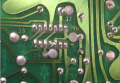
The negative reference voltage was pretty close to spec. but the zero was way off. From a missing screw it was obvious that I was not the first person to take a peek inside. In fact...
IMG_1008[1].JPG
Dunno just what the heck the back to back transitors are being used for, diode? Plus, several of the 8 pin ICs have obviously been hand soldered without cleaning. Didn't take any pics of the front side but all the caps look good, at least not leaking.

Turns out the "calibration" of the scope screen to the 501 tester is not needed with today's DSOs. It is a simple matter to set the scope up in XY mode with the scaling done by the scope once you get the hang of it. The ability to invert inputs really helps.

The board has nice large and numbered test point pads but nothing to connect to. The board calibration required soldering shorting jumpers to test pads and a piece of wire to attach the DMM. The manual mentions a full diagnostic with notes and scope screenshots for troubleshooting but it isn't in the manual.
1656981195705.png
Also some odd solder bridges between IC pins here and there but most seem unused, but still...
 
Top