Automotive Brake and Signal Light converter

Thread Starter

SENWI

Joined Nov 1, 2022
12
Good day folks. Brand new to the group. I am retired and now a tinkerer. I intend to get a lot more into electronics focusing on home automation and look forward to reading and learning as I hangout in the background.

But the more urgent reason I found this site is that I am in desperate need of converting a 3 wire brake and turn signal system to a 2 wire combined brake turn signal system. I have now bought three different controllers and none have worked correctly. This last one is the only one where the circuit board has been accessible and I was hoping for some help in translating its function into something I can understand.

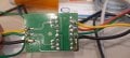
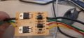
I have attached photo of front/back. Side with 4 wires is supposed to be the side fed by the vehicle. So black would be DC- and the yellow (left turn signal), red (brake lights), and green (right turn signal) would each be fed with DC12V+depending on which was active on the vehicle. Then the magic of the circuit board is that it is supposed to merge the brake signal into each turn signal, as the same bulb element is used for both functions on a trailer.

When I feed 12V to the vehicle side yellow/green/or red, I do not get any voltage output from the center pin of the transistors leading to the trailer side green or yellow. Interestingly, when I feed 12V pwr the opposite way (to the trailer side yellow or green), then I do get 12V to the corresponding vehicle side yellow or green and also red.

I am quite new to electronics. I know how to read (most) resistors, I understand function and polarity of diodes, Generally know how to use a meter. I have confirmed that when I do feed the power from the vehicle three wire side (one with red), that I do get 12V to the outside pins on both transistors. But only mV from either center pin.

Any assistance would be most appreciated. If you need me to draw this out I will do my best.
 

Attachments

crutschow

Joined Mar 14, 2008
34,428
Can't really tell much without a schematic.
If you could trace out the complete circuit that would be a big help.
But there seems to be no markings on the transistors(?) so that could be a problem.
 

Thread Starter

SENWI

Joined Nov 1, 2022
12
Can't really tell much without a schematic.
If you could trace out the complete circuit that would be a big help.
But there seems to be no markings on the transistors(?) so that could be a problem.
I will do what I can and post something tomorrow - thanks
 

crutschow

Joined Mar 14, 2008
34,428
Don't know if this will help, but here's the LTspice simulation of a circuit that combines the separate turn and stop-light signals into one output.
It's basically a power XOR gate (output high when one input but not both are high) that uses P-MOSFET transistors.
It may be similar to what you have.

Note: If this is similar to the circuit you have then either the turn-signal or the brake signal must be connected to ground for the test (normally through the vehicle lamp's filament when off), since one input must be high and one low to get an output.
That may be your problem.

1667399424128.png
 
Last edited:

crutschow

Joined Mar 14, 2008
34,428
The color (especially yellow) is hard to read (color is normally not used for schematics), but I think my premise is correct.
You need to ground one of the inputs when you apply voltage to the other (for example, ground the turn signals when you apply brake voltage or vise-versa).
 

Thread Starter

SENWI

Joined Nov 1, 2022
12
The color (especially yellow) is hard to read (color is normally not used for schematics), but I think my premise is correct.
You need to ground one of the inputs when you apply voltage to the other (for example, ground the turn signals when you apply brake voltage or vise-versa).
Sorry for colour, was trying to keep right and left signals identified.

I am not sure what you are suggesting. The ground (-) is a pass through signal from vehicle to trailer. On trailer, each bulb is grounded on one side of element. The circuit board is just switching the + side.

???
 

shortbus

Joined Sep 30, 2009
10,045
The color (especially yellow) is hard to read (color is normally not used for schematics), but I think my premise is correct.
It is if you put a few periods spaced at the bottom of your post. Red is the favorite schematic color.

What I mean by the periods comment -
.
.
.
.
 

crutschow

Joined Mar 14, 2008
34,428
I am not sure what you are suggesting.
I'm not sure how you are testing the circuit, but the inputs that are not at 12V need a path to ground.
If you apply 12V to all inputs or leave any of the inputs floating, the circuit will not work (as you observed).
The circuit ground connection has nothing to do with that.

Look at my simulation.
There is an output only when one input is high and the other is low (ground), not just open.
The low is provided by the bulb filament in your vehicle that goes to ground (which has a very low resistance when off).
Make sense?
 

Thread Starter

SENWI

Joined Nov 1, 2022
12
I'm not sure how you are testing the circuit, but the inputs that are not at 12V need a path to ground.
If you apply 12V to all inputs or leave any of the inputs floating, the circuit will not work (as you observed).
The circuit ground connection has nothing to do with that.

Look at my simulation.
There is an output only when one input is high and the other is low (ground), not just open.
The low is provided by the bulb filament in your vehicle that goes to ground (which has a very low resistance when off).
Make sense?
.
.
Thank you for your continued assistance. I am testing two different ways, on vehicle with trailer attached, and with a 12V pwr source at desk. At desk I am connecting power source to one of the R/Y/or G leads and the black neg. I then connect a bulb to the corresponding G or Y out of transistors and the black neg. None of these arrangements light up any bulbs. Yet when I check the vehicle side input to this controller, I am getting proper voltage. (12V between ground and any of the R/Y/G terminals)

This is a European land rover (out of Italy) and has a standard 13 pin round European towing connector. I am trying to use the above controller to plug into stock 13 pin port and convert to a 7 pin USA towing connector. The controller is needed to combine the source separate brake and turn signals to one.

So at this point I am lost. Either this controller is faulty (3rd one) or there is something different re European vs USA towing circuits???
 

Attachments

geekoftheweek

Joined Oct 6, 2013
1,215
I know you probably don't want to buy another converter, but I found this one earlier for another fellow. Unlike all the other "converters" available that I looked at this one draws power from the battery for the trailer lights. Your incoming wires are only used for switching signals. I don't have experience myself, but the reviews seemed promising. https://www.etrailer.com/Trailer-Wiring/CURT/C56496.html?feed=npn&utm_source=google&utm_medium=cpc&utm_campaign=Google | Shop - Trailer Wiring&adgroupid=128484934262&campaignid=15586143335&creative=569877447301&device=c&devicemodel=&feeditemid=&keyword=&loc_interest_ms=&loc_physical_ms=9015028&matchtype=&network=g&placement=&position=&gclid=EAIaIQobChMIx6ua8YfQ9wIV1gorCh1Uig0nEAQYASABEgLKyPD_BwE

Sure it's not as much fun as building your own, but in the long run having your trailer powered separate from your vehicle lights instead of piggy backed on to them will help avoid some issues in the end.
 

Thread Starter

SENWI

Joined Nov 1, 2022
12
You still haven't done what I asked.
While using the external supply, ground all the input leads, except for the one that you apply 12V to.
.
.
.
Very Sorry Zapper, did not understand till now what you meant. Yes this works for all permutations.

How do I incorporate this into the vehicle now. The input leads from vehicle are not going to be grounded, when not energized. Do I need to modify circuitry or is this controller not right for my vehicle needs.

Sorry, the grounding of the 'hot's' is beyond my electrical knowledge now.
 

Thread Starter

SENWI

Joined Nov 1, 2022
12
I know you probably don't want to buy another converter, but I found this one earlier for another fellow. Unlike all the other "converters" available that I looked at this one draws power from the battery for the trailer lights. Your incoming wires are only used for switching signals. I don't have experience myself, but the reviews seemed promising. https://www.etrailer.com/Trailer-Wiring/CURT/C56496.html?feed=npn&utm_source=google&utm_medium=cpc&utm_campaign=Google | Shop - Trailer Wiring&adgroupid=128484934262&campaignid=15586143335&creative=569877447301&device=c&devicemodel=&feeditemid=&keyword=&loc_interest_ms=&loc_physical_ms=9015028&matchtype=&network=g&placement=&position=&gclid=EAIaIQobChMIx6ua8YfQ9wIV1gorCh1Uig0nEAQYASABEgLKyPD_BwE

Sure it's not as much fun as building your own, but in the long run having your trailer powered separate from your vehicle lights instead of piggy backed on to them will help avoid some issues in the end.
.
.
.
Thanks. This is probably a good option for a lot of vehicles. I am not sure it works with a Range Rover as on the rover all of the circuits are monitored by the computer. The vehicle harness would need to monitor the power supply in addition to signal switching. It checks for shorts, burnt out bulbs, etc.
 

crutschow

Joined Mar 14, 2008
34,428
How do I incorporate this into the vehicle now.
The bulbs in the vehicle should provide the ground through the cold filaments when the signal is off, unless your vehicle has LED lighting, which could be a problem.
If so, the addition of a low value resistor to ground at each input may be a solution.
 
Last edited:

Thread Starter

SENWI

Joined Nov 1, 2022
12
The bulbs in the vehicle should provide the ground through the cold filaments when the signal is off, unless your vehicle has LED lighting which could be a problem.
If so, the addition of a low value resistor to ground at each input may be a solution.
.
.
Yes vehicle and trailer have LED. What size of resistor do you recommend? And is this what you mean?

1667510762044.png
 

crutschow

Joined Mar 14, 2008
34,428
What size of resistor do you recommend?
It would likely have to be in the few hundred ohm range.
Do you have any resistors or a variable potentiometer you can try?
If so, apply power to one of the turn signal inputs while trying different values from the brake terminal to ground (no applied power there) to see what the highest value is that works.
The lower the value the more power it will have to dissipate when that terminal has 12V applied.
Edit: You could also add a small incandescent 14V automobile bulb (such as one of these) from each terminal to ground.
is this what you mean?
Yes.
 
Last edited:
Top