automatic servo controller using 555 chip?

Thread Starter

Mattman1982

Joined May 7, 2014
7
Hey all

This is my first post here. Have been browsing the internet working on a project and found that alot of my answers were coming from this forum so figured I'd just ask you guys ;)

Well I have a servo controller that uses a pot and 555 chip to move it from one extreme to the other (like this http://makezine.com/projects/control-a-servo-motor-without-programming/)

Well what I want to do is make an "automatic mode" that moves the servo from one extreme to the other by itself, and adjust the frequency with another pot. I've been leaning the way of using a sine-wave input (like this http://www.engineersgarage.com/tutorials/circuit-design-frequency-modulated-waveform-generation) into a digital pot (MCP41XXX) to control the automatic motion and a pot to control frequency. If I do this I'll have to worry about controlling the digital pot with SPI interface and all that mess though.

Can I do this with just 555 chips or should I just use a programmable logic controller? I have some experience with the PIC18 family. thanks!
 

Thread Starter

Mattman1982

Joined May 7, 2014
7
any thoughts at all?

I'm thinking I will have to go the way of a PLC, but would have been nice and simple if I could do it with a few 555's

thanks

Matt
 

#12

Joined Nov 30, 2010
18,224
This seems a very strange servo-motor to me. Point being, we could use some details.

It seems to me that if you give the control pin a square wave of frequency 50 Hz and the time that the pulses are high is changed from .5 milliseconds to 2 milliseconds, the servo-motor will change its position by 180 degrees, moving clockwise as viewed from the front. Assuming this is a linear function and reversible, true?

If this description is true, some people here would be able to work with this idea.
If it's false, please correct me.
 

Thread Starter

Mattman1982

Joined May 7, 2014
7
Yes that's the solution I started with however I want the servo to move from 0 to 180 very slowly, like 4 seconds which is why I'm looking at a sine or maybe triangle wave. Thanks for reply
 

#12

Joined Nov 30, 2010
18,224
OK. We're communicating.
How fast does the servo normally move if you give it a step function?
In other words, how many pulses will happen between the left position and the right position when you change the "on" duration from .5 millisecond to 2 milliseconds?

I am arriving at: The "on" time must be changed from .5 ms to 2 ms in a duration of 4 seconds. That's 200 cycles of the square wave, right?
 

Thread Starter

Mattman1982

Joined May 7, 2014
7
Yes but can you break the square wave pulse into 200 gradually increasing steps? I want the servo to very slowly move is why I'm thinking triangle wave?
 

djsfantasi

Joined Apr 11, 2010
9,237
An Arduino Uno can do this easily as well. It comes with a servo library which includes a demo sketch (program) named Sweep, which sweeps a servo back and forth. Adding a pot to an ADC pin and calculating the delay, based on the pot value, between moves of the RC would work.
 

djsfantasi

Joined Apr 11, 2010
9,237
Yes but can you break the square wave pulse into 200 gradually increasing steps? I want the servo to very slowly move is why I'm thinking triangle wave?
No, you control speed by how fast you change the on time of the square wave pulse. The amplitude of the signal pulses have no effect, except not work if they are too low.
 

Bernard

Joined Aug 7, 2008
5,784
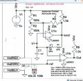
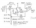
Another way is to use a voltage controlled PWM ckt. & use a triangle wave sig.with period of 8 sec. for the voltage control. The fun part is adjusting amplitudes & offsets to give desired rotation. A LM339 quad comparator might do.
 

Attachments

Last edited:

djsfantasi

Joined Apr 11, 2010
9,237
Bernard,

What thread did that circuit orignally come from?

I would like to understand the circuit better.

dj
 
Last edited:

Bernard

Joined Aug 7, 2008
5,784
Guess we'll have to ask the Sgt. can't seem to find the source but believe it is from about 2012. Also similar from Bill's Index.
 

Bernard

Joined Aug 7, 2008
5,784
Maybe Sgt Wookie's files are in better shape than mine. Found this circuit that I believe was used to adjust amplitude & offset from triangular wave as input to final comparator of a V controlled PWM signal generator. Wirh some value changes and additions might make a servo controller. ' be back next week.
 

ronv

Joined Nov 12, 2008
3,770
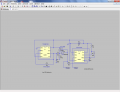
Here is a 555 implementation. The first one generates the triangle wave. The second one the servo pulses. The op amp doesn't have to bee the one I used but it does need to be rail to rail.
All of these servos I have seen use 1ms to 2ms pulses with 1.5 being center. I'm not sure where the .5 came from in the link.
One thing I see is it starts with a bias to one direction and take a few cycles to center.
May take some tweeks to adjust for tolerances. :eek:

It should probably be a CMOS 555 like TLC555.
 

Attachments

Last edited:
Top