If the wires, or the contact points, are not 100% it won't work and/or it may blow something right? Even if it works, this is not a long term solution. I need a proper 12 V cell that can be adjusted. (The chickens here wait until it's dark until they go in - they enjoy life outside too much) When you enter '12 V photo cell' in Google however you get the same shit. The one I bought was actually the more expensive model. Cheaper ones cost less than $ 2.
Ah, that's like jumping off a bridge with a faulty bungy cord and just before you hit the ground and die somebody yells 'Don't worry dude, I changed the cord, the one you were going to jump with was no good!'
I have plenty of confidence when I can, in this case at least, follow the instructions. But the stuff is simply too small for me. My fingers are fairly big too.
I do everything myself. I maintain the cars, I do a better job than a plumber, I can build speakers and shop interiors, grow my own food. I like to do things. I just start 'whatever' and see how it goes. But electronics is not like mechanics. You can take a pump apart and study it but to be able to understand the things you (and many other forum members) are good at, a study is very important. And experience counts too. With mechanics there is more logic involved in the sense that you can see it. Now I am doing things and not really learning, I am just doing what a helpful person is telling me to do.
Right, small existing black to - power supply and small existing red to + power supply.
Brown is black so goes to + transformer. Yellow/green is red so goes to relay as power.
No wonder I am not such a good cook. My father was married to an Indonesian. Her cooking was more interesting than heaven with 40 virgins and every time I asked her how the heck she did it she said 'It's very simple, just a bit of this and that'.
Well, tell me what 12 V cell I should buy. Even if this works, it's crap. Chinese junk you say. Ok, but junk to me means cheap things that work but never for long. Depending on the purpose and your budget junk can be fine. If you can buy a cell for next to nothing and it works for 6 months or a year that's alright. You just buy 2 and simply replace it after that time. These things are produced in enormous quantities, sold as 12V and then you need a Chinese kid to rewire them? That just doesn't make sense. When you look in and around the house you'll find that an awful lot of things were made in China. Your phone, TV, all sorts of electronics really and usually they work fine. Not for ever but that's no problem, you never paid much anyway. But yeah, I am in for a better quality photo cell for sure!
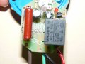
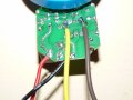
You seem to be jumping round the different problems you have rather than solving one at a time. I started by trying to solve the sensor problem. Your pictures are confusing as you seem to have different sensors. Some have three wires and some have four. some have 4 diodes and a 150 ohm resistor fitted. I think the one with the diodes and resistor fitted are designed for a 230 volts AC supply. On the picture with 4 wires the red wire is the common relay contact (C). The black wire is the relay normally open contact (NO). On the assumption that the relay coil is driven by a NPN transistor or N channel mosfet the yellow is the positive supply to the electronics and the brown wire the positive supply to the electronics. It would be easier if you attached your pictures to the relevant posts rather putting them on a website with no way to refer to individual pictures. (Other than having to count them.)
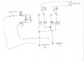
As you seemed to have moved to the actuator and DPDT relay wiring I have attached a diagram using a switch in place of the sensor.
This is the same as the fifth picture from the start of the website but with a switch in place of the sensor.
This is a link to the datasheet on your DPDT (Double pole double throw.) relay
Edit to correct my error spotted by "anniel747". Where I said " the brown wire the positive supply to the electronics." should have been the brown wire the Negative supply to the electronics.
I have just started reading the instructions again. (and see you posted a new message) No, both cells are exactly the same. Inside and outside. The components inside are 100% equal. Both have 3 wires (perhaps difficult to see in the pictures) At first I uploaded the pics on my website because I am used to a chicken forum where you cannot upload pictures but here you can, I noticed later.
Both have a green, red and black wire.
I am now here: green wire cut off. And a yellow and a brown wire soldered.
The data sheet is from OMRON. I was asked to post a data sheet from my relay (which has the same number) but is not an OMRON. It's OMROTI. And as there is no data sheet from 'OMROTI' I didn't post it.

 Facebook
 Google
 GitHub
 Linkedin