But it's often inevitable. You buy a desktop computer it's made in China. The laptop too. The speakers. Nearly all phones are made in China. Quality ones (and expensive) like Apple even. Car parts for the most as well. When cleaning our new sofa last year I saw a Chinese label. (to my BIG surprise!) Tools for non professionals, even dog treats, it's almost impossible to escape. Many parts sold locally are also imported, you just get them quicker. If you have to solder something once in your life time you'll go for the cheapest. If you have a car and it needs new tyres you go for the cheapest if you want to sell it within a few months. Then there are billions in this world (Africa) who want a fridge, a TV but have very little money so they go for the cheapest, China again .....
Ah Canada! My mums husband was offered a temp. job there. I think in Montreal. He kept telling everybody for years and years. He was also impressed by the bitter cold but said there were REAL shopping centres (unlike in the Netherlands) where you could get ANYTHING and it was always nice and warm. An ex-colleague of mine tried for years and years to get into the country, he absolutely loved it but never managed to get residency.
Many years later my mums husband went back, with my mum. Made a trip and told us how unbelievably BIG it was. I know of course. I love geography, got a large globe on my desk and spent 2 years in Oz. Big and empty too. But nice and WARM!
Nah, the Netherlands is not that cold really but I got fed up with it. I left when I was 26, came back a few times and decided the drizzle was not for me. We live in Spain now, on the east coast and there is rarely a day without a deep blue sky. The main problem here is the lack of rain. For me a wonderful 'problem'. I still appreciate it. Much happier here.
''When new wires in place, small black to - power supply and small red + power supply.''
That is clear and I did that.
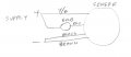
Then you said ''For the large wires follow this ('this' means the diagram that shows how to connect the cell and the relay and the actuator) while disregarding the white:''
Then you wrote: ''BROWN IS BLACK, YELLOW/GREEN IS RED.''
Ok, so if brown is black, that black goes to the + transformer, as in the diagram.
If yellow/green is red, that yellow/green goes to the relay as power.
Hi anniel, Thanks for spotting my error in post #175. I agree with the polarity for the yellow/green and brown wires in post #188 but that contradicts post #169.
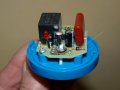
Sofa, In the picture in post #177 can you confirm that there is a link soldered in place on the right hand side shorting out the large brown capacitor. (I think this is part of a modification made to a 230 volt AC version to make it work on 12 volts DC.) Also can you read the part number on the glass diode at the end of that capacitor ?
Les, the diodes I removed are numbered 1 2 3 4 at the top and 5 6 7 8 at the bottom. The original connection was 1 5 - 2 6 - 3 7 and 4 8.
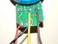
Pin 5 now has a brown wire soldered and Pin 8 a yellow/green wire. The solder of pin 8 MAY touch the solder from pin 7.
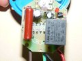
I have not touched the large brown capacitator.
The code on the brown capacitator is: RFE 334K 630V MDD
Next to it is a small 'drum' with the code 100 uF and 35V
Looking at the small red LED top right: at 7 pm from there is another small drum but so small that even with a magnifier it's NOT clear what it says: HDF VEN T 105 Celsius ???
In that case brown (which is meant to be black) goes to + transformer.
Yellow/green (which is meant to be red) goes to – transformer.
That leaves me with the original black and red. (Post 133) original black goes to + transformer and original red goes to the relay.
If you and Les agree I am happy to try - just want to avoid blowing up something. He also mentioned the brown capacitator but I haven't touched that one at all!
I’d also like to say something about the American who made the diagram with the cheap photo cell, the cheap relay and the actuator. He says a heavy duty relay is a better option but then again, the cheap one is so cheap that it doesn’t really matter. You just pop in another. He says about the photo cell that they are not reliable and asks if anyone knows a better alternative. That indicates the problem too, they’re mostly cheap and mostly made in China. Apparently it’s not so easy getting a reliable cell for a reasonable price.
But, he made these systems and even if the quality is disputable that doesn’t mean they never work. I got the same cells, 2 of them. Both rated at 12V and they absolutely do NOT work. Not with an actuator, not with a car bulb.
The assumption that all parts were rubbish was hard to believe too and indeed, upon Anniel’s advice they both lit up in the end.
And then there are the 12V cells that leave the factory by the millions but have to be modified else they're rubbish (they are anyway) ........ I just find it all weird.
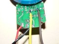
From the wire colours shown in the picture in post #177 try connecting the sensor like this,
Below is one of your pictures with an arrow pointing to the diode. I originally thought that it was a zener diode to clamp the output of the power supply part of the 230 volt AC version. (I can't trace the tracks on that part of the board as they are in shadow.) The white item just behind the potentiometer with black sleeve on one of it's legs is the actual LDR sensor which needs to be covered to make the unit think it is dark.
Edit. I have just seen some posts that appeared sin I started this post. You can try what you were planning to do in post #207 but you don't give enough detail for me to know what you are doing as you have not posted a diagram (Schematic,) I suspect you are trying to drive the external relay coil rather than a bulb.
Les.

 Facebook
 Google
 GitHub
 Linkedin