 Facebook
 Google
 GitHub
 Linkedin
Hello everyone!
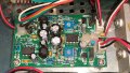
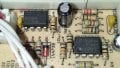
Im having a problem... I got nice lighting installed in my new studio, but the lighting of my laser is controlled by audio with an onboard microphone.
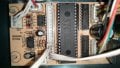
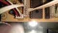
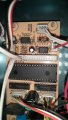
This is annoying because i want the laser to work also when my music isnt that loud. inside the laser is a tiny microphone on a PCB.
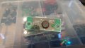
What a want is to create a jack input on the laser so i can take the 0dB output of my audio interface and send that directly to the laser.
does anyone know how i can get the line level down to the level of the PCB mic so i can solder the jack input on the laser to the + and - of the microphone?
Would be lovely to get helped <3
Im having a problem... I got nice lighting installed in my new studio, but the lighting of my laser is controlled by audio with an onboard microphone.
This is annoying because i want the laser to work also when my music isnt that loud. inside the laser is a tiny microphone on a PCB.
What a want is to create a jack input on the laser so i can take the 0dB output of my audio interface and send that directly to the laser.
does anyone know how i can get the line level down to the level of the PCB mic so i can solder the jack input on the laser to the + and - of the microphone?
Would be lovely to get helped <3
")


