[Beginner question] Buffering line level audio and shifting to 0..-15V

Thread Starter

gabz

Joined Jul 4, 2022
4
Hi there,
to start with, this is my first circuit that goes beyond voltage dividers and regulators, so I'm quite unsure what to do and rely heavily on simulation with everycircuit.com.
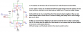
My goal is to buffer a stereo line level audio signal without dumping the signal into my circuit and distorting it (goes to an amplifier, my circuit just grabs the signal). First stage is to decouple the signal and sum it, second stage is used to amplify it and add a negative DC offset.
Need to drive a EM80 tube from the audio signal, thats all.
Before I start ordering the components, it would be nice if anyone could just have an eye on the circuit. Quite possible i took the completely wrong direction and nothing works as intended x.x
Btw this is my first circuit design, so i might have ignored one or another conventions.

All the capacitor/resistor values are based on simulation.

Best
Gabriel

Screenshot 2022-07-04 at 14.03.46.png
 

Papabravo

Joined Feb 24, 2006
21,094
A couple of things:
  1. A 741 does not really play well in single supply mode, you should choose a more recently designed part if you want to do this.
  2. The output will not swing all the way to the power supply rails. Again you should use a recently designed part that is characterized to swing rail-to-rail.
  3. Opamp inputs need a DC path to GROUND for proper operation.
 

Thread Starter

gabz

Joined Jul 4, 2022
4
Thank you for the response!
I took the 741 because it's the component that comes to mind when thinking of an opamp. But I'm gonna source another one then.
Didn't know about dc grounding at the inputs, is it ok to just pull them to ground with a 10k?
 

Sensacell

Joined Jun 19, 2012
3,420
If you have a bi-polar plus and minus 15 V split supply, use it to power your opamps so they can make use of this supply range.
As mentioned in post #4, use a resistive summing amp circuit.
All opamp inputs need a DC bias path, just connecting a capacitor provides no DC path.
IF you use a split supply, you can bias an input to 0V with a high value resistor (100K)

You could accomplish all of the functions with one opamp.

Use an inverting summing amp with capacitive input coupling.
Bias the non-inverting input to your desired negative bias point for the tube.
Set the gain by adjusting the feedback resistor.
 

Thread Starter

gabz

Joined Jul 4, 2022
4
If you have a bi-polar plus and minus 15 V split supply, use it to power your opamps so they can make use of this supply range.
As mentioned in post #4, use a resistive summing amp circuit.
All opamp inputs need a DC bias path, just connecting a capacitor provides no DC path.
IF you use a split supply, you can bias an input to 0V with a high value resistor (100K)

You could accomplish all of the functions with one opamp.

Use an inverting summing amp with capacitive input coupling.
Bias the non-inverting input to your desired negative bias point for the tube.
Set the gain by adjusting the feedback resistor.
Wouldn't summing the signal directly at the line level affect it and what gets to the audio amplifier? As mentioned, the circuit itself should have minimal impact on the signal. That was the primary reason i was buffering both channels to sum them after the first opamp stage. But I might also be on the completely wrong track here, as I said, absolute beginner :D
 

Sensacell

Joined Jun 19, 2012
3,420
Wouldn't summing the signal directly at the line level affect it and what gets to the audio amplifier? As mentioned, the circuit itself should have minimal impact on the signal. That was the primary reason i was buffering both channels to sum them after the first opamp stage. But I might also be on the completely wrong track here, as I said, absolute beginner :D
The signals sum at the summing node of the opamp, (the inverting input) this point is at ground. The inputs "look" like a resistor to ground from the amplifier's POV. As long as the input resistors are a high enough value (~10k?) the signal will only be slightly attenuated.

If your signal source is very high impedance, add opamp follower buffers before the summer, with a 1meg bias resistor to ground for that all-important input bias.
 

crutschow

Joined Mar 14, 2008
34,201
You said you rely heavily on simulation, but it's apparent you did not simulate any of your circuit or you would have seen the problems.
 

Thread Starter

gabz

Joined Jul 4, 2022
4
You said you rely heavily on simulation, but it's apparent you did not simulate any of your circuit or you would have seen the problems.
Well, as i said i'm using everycircuit.com, i don't know about the quality of this simulator. No need to get offensive here.

However, i opted for a mono electret microphone in combination with a LM386 and RC lowpass at the output, biased it to negative voltage. This works surprisingly well in combination with the EM80 tube, so i guess problem solved.

Thank you for your help
 

MrChips

Joined Oct 2, 2009
30,621
Well, as i said i'm using everycircuit.com, i don't know about the quality of this simulator. No need to get offensive here.

However, i opted for a mono electret microphone in combination with a LM386 and RC lowpass at the output, biased it to negative voltage. This works surprisingly well in combination with the EM80 tube, so i guess problem solved.

Thank you for your help
FYI

LM386 is not an appropriate IC to use for this application. LM386 is a 125mW audio amplifier designed for driving loudspeakers.
In your case the high distortion on the output does not matter because for the purpose of driving the EM80 magic eye tube it doesn't care.

It is possible that a simple voltage divider input followed by a one transistor amplifier would probably work just as well.
 
Top