Facebook
 Google
 GitHub
 Linkedin
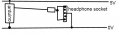
I have a simple circuit. An audio signal is generated by atmega328p (arduino nano). The signal is PWM at 62.5kHz. In the other end I have a headphone socket and my ear plugs connected.
I have now made the following observations:
1) connecting the PWM signal directly to the headphone socket: Sound is good and loud!
2) connecting the PWM signal via 220 ohm to the headphone socket: Sound is good and now volume is decreased.
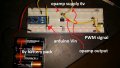
3) connecting the PWM signal to a voltage follower and the opamp output to the headphone socket: No sound!
4) connecting the PWM signal to a voltage follower and the opamp output to a 220 ohm resistor and then to headphone socket: Sound "seems like it has passed a low pass filter" and volume is decreased (compared to bullet 1)!
My opamp is TS922 and VCC is connected to 6V and -VCC to 0V (same 0V as headphones).
I need some help about what is going on. Here is my own thoughts:
reg. 1) -> I guess the mechanics in the speaker "evens out" the pwm signal. It sounds like it is not necessary with a low pass filter to smooth the signal at all (that actually surprised me!).
reg 2) -> Intuitively I guess it makes sense that the voltage is decrease since the current is limited by the resistor - but to be honest I am not quite sure whats going on.
reg 3) -> This one I simply does not understand. I would have expected same result as in 1)
reg 4) -> Totally confused. Why does adding a 220 ohm resistor suddenly produce sound!?
I hope some of you can help me out") thanks.
thanks.
I have now made the following observations:
1) connecting the PWM signal directly to the headphone socket: Sound is good and loud!
2) connecting the PWM signal via 220 ohm to the headphone socket: Sound is good and now volume is decreased.
3) connecting the PWM signal to a voltage follower and the opamp output to the headphone socket: No sound!
4) connecting the PWM signal to a voltage follower and the opamp output to a 220 ohm resistor and then to headphone socket: Sound "seems like it has passed a low pass filter" and volume is decreased (compared to bullet 1)!
My opamp is TS922 and VCC is connected to 6V and -VCC to 0V (same 0V as headphones).
I need some help about what is going on. Here is my own thoughts:
reg. 1) -> I guess the mechanics in the speaker "evens out" the pwm signal. It sounds like it is not necessary with a low pass filter to smooth the signal at all (that actually surprised me!).
reg 2) -> Intuitively I guess it makes sense that the voltage is decrease since the current is limited by the resistor - but to be honest I am not quite sure whats going on.
reg 3) -> This one I simply does not understand. I would have expected same result as in 1)
reg 4) -> Totally confused. Why does adding a 220 ohm resistor suddenly produce sound!?
I hope some of you can help me out
thanks.