 Facebook
 Google
 GitHub
 Linkedin
Audioguru again
- Joined Oct 21, 2019
- 6,826
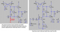
The original circuit is missing a resistor or the preamp transistor at the base of Q3 to Vee.
It is also missing AC and DC negative feedback that all audio amplifiers have.
The simulation should show the DC voltages at the emitters of the output transistors instead of power, then you will see that there is no way the output transistors will have their base voltages near 0V.
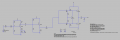
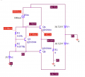
Here is a similar simplified circuit I simulated but the little transistors might be overloaded.
It is also missing AC and DC negative feedback that all audio amplifiers have.
The simulation should show the DC voltages at the emitters of the output transistors instead of power, then you will see that there is no way the output transistors will have their base voltages near 0V.
Here is a similar simplified circuit I simulated but the little transistors might be overloaded.
Attachments
-
 139.5 KB Views: 15
 -
 39 KB Views: 14


")


