Audio amplifier opinion

Thread Starter

ArakelTheDragon

Joined Nov 18, 2016
1,366
What do you think about this audio amplifier with 1 transistor. I intend to replace LM324 with TDA2030, any suggestions for the transistor are welcomed. There will be about "2V", "1A" power over the transistor, so a small iron is in order to cool it off? I think the OPAMP is good without an iron.

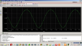
EDIT: It bothers me that the sinusoid has a very small margin (peak to peak), will that be ok? Will it be better to use 2 transistors (NPN and PNP), suggestions about transistors and orcad gives me bad results when I try to do it with 2 transistors? I think there should be "1.2V" pre-voltage for class AB work. But Orcad gives me a bad sinusoid, I will post the graphic when I can.
 

Attachments

Dodgydave

Joined Jun 22, 2012
11,395
There are far better chips than the TDA2020 /50 series, that give better frequency response, the tda chips dont need a power transistor slave.
 

AnalogKid

Joined Aug 1, 2013
12,128
As you can see in both the current and voltage waveforms, there is increasing harmonic distortion in the positive half-cycles due to the gain of the transistor decreasing as its collector current increases.

This is a very poor amplifier design. There is over 1/2 amp of static current through the speaker. This is more than enough to cause its cone to be WAY off center in its travel range, almost certainly causing it to "bottom out". That is when the voice coil bangs into part of the magnet structure.

Consider replacing the entire circuit with an LM386.

R3 has no purpose and can be removed.

ak
 

Audioguru

Joined Dec 20, 2007
11,248
Audio amplifiers have plenty of negative feedback from the output to the inverting input. The negative feedback causes the distortion to be so low it is hard to measure. Your circuit has no negative feedback.
 

Bordodynov

Joined May 20, 2015
3,431
Hello ArakelTheDragon. Do not be offended, but what you painted is delirium. This is forgivable for beginners. Operational amplifiers are commonly used with feedback. The transmission ratio for combining the inverting and non-inverting inputs is the common-mode signal transfer coefficient. Some speakers will not like direct current. This current will greatly dislodge the membrane and this will cause large distortions. In real circuits, either separating capacitors or bipolar power are used. And further. Do not completely trust the results of the calculations. After all, the developer of the operational amplifier model, only in a terrible dream would you see your project.
 

Audioguru

Joined Dec 20, 2007
11,248
You never ever feed both inputs of an opamp with the same signal!
An opamp input must be biased at an input voltage so that it can swing equally up and down.
All audio amplifiers have negative feedback from the output to the (-) input of the opamp.
The LM324 (and its sister the LM358) have crossover distortion, too much noise and a poor high frequency slew rate to be used in an audio amplifier.
An audio amplifier almost always has two output transistors with one pulling the output up and the other pushing the output down called "push-pull". Then when there is no input signal they both do not conduct much current so they stay cool. But your amplifier with only one output transistor has a high current in the output transistor all the time so it will get hot and waste the battery power away.
 

Bordodynov

Joined May 20, 2015
3,431
You never ever feed both inputs of an opamp with the same signal!
An opamp input must be biased at an input voltage so that it can swing equally up and down.
All audio amplifiers have negative feedback from the output to the (-) input of the opamp.
The LM324 (and its sister the LM358) have crossover distortion, too much noise and a poor high frequency slew rate to be used in an audio amplifier.
An audio amplifier almost always has two output transistors with one pulling the output up and the other pushing the output down called "push-pull". Then when there is no input signal they both do not conduct much current so they stay cool. But your amplifier with only one output transistor has a high current in the output transistor all the time so it will get hot and waste the battery power away.
Entering the output stage into Class A mode with the help of an additional resistor (in this case 1 kΩ) removes cross distortion. I built a transistor model of these operational amplifiers. This model well imitates cross-distortion. Also, the addition of a resistor removes the cross distortion provided that the load current does not exceed the current of the additional resistor. At a load of 100 kΩ, no distortion gives an internal 50 μA current generator.
 

GopherT

Joined Nov 23, 2012
8,009
Connecting the two op amp inputs to the same signal is how you would test “common mode rejection” of the amplifier. Ideally it would be a zero output signal.

Why are you connecting the amplifier this way?
 
Top