hi guys, so i've been playing for a while and the simulation works is pretty much working as expected somewhat elated as 3 days ago i didn't think this would happen ^^
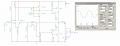
main issue is i'm getting some peak clipping when input signal goes above 400mV peak, which is about 6V rms at the output. anything above this clips.
im pretty sure this is just as its reached its maximum output voltage so is behaving as would be expected. when its not 3 am ill go grab a calculator and check that it has reached its peak voltage and current limits, but at a glance it seems like it.
i'd like to be able to use it with consumer line in products which would make the input peak voltage about 450mV. Is this just a case of recalculating with a gain of say 18 so as to allow for a slightly larger input signal?
have attached an image of it clipping at a 7.46 rms when a 1v pk-pk signal is input, its using calculated values on the caps at the moment as i was playing around to see how changes affected bandwidth etc. ignore the slightly peculiar waveform, its a particularly old and inefficient simulation package that always gets a bit funny with the scope on, the weirdness on the first peak is just it starting to redraw the curve.....
will do some research as soon as i've got time, got another assignment to finish off, but that shouldn't take too long. i'm assuming i will need to do some recalculations once i've added it due to increased load impedance.
peak clipping of larger input signals was an easy fix, just raised the resistance of r6 in the diagram above to about 1.8k and it all seems fine
Coollestersmooth can you tell me where I can buy a 577nF, 210μF, 177pF, 4000μF and 60kΩ resistor ??
You never heard about "standard values"?
For resistors use E24 series
E24: 10 11 12 13 15 16 18 20 22 24 27 30 33 36 39 43 47 51 56 62 68 75 82 91
And for capacitors E6
E6: 10 15 22 33 47 68
As you can see 577nF don't exist, you can buy 680nF or 470nF as for 60kΩ use 62 or 58 etc.
i did specifically write in the post that i was using exact calculated values as i was playing around to see how changes in the values for capacitors etc affected bandwidth etc. it was 3 am and i couldn't be bothered changing them back just to post a screen shot of peak clipping and output values, i am aware that i will have to use marketplace available resistors etc. However i shall have a look at the specific cap and resistor series you mention, was just going to use aluminium electrolytic smd caps rated at 50v+ where possible, foil/film where smaller values were required and the giant bucket of resistors we have in the lab for everything but the output power resistors. ^^
hmmmm, so doing some modeling for the circuit, adding in the inductive part of the load massively reduces current at the output. :S
currently modeling with a resistor in series with an inductor for the load impedance (rough approximation of the speaker)
current has dropped from about 1.75A to 15mA! im imagining this is going to cause problems?
not sure if my zobel network is correct either, i think i may be missing a resistor connecting the load impedance to before the output pair ala R3 in figure 27 of studiots post above (post #147)
so with the zobel network in place most of my current is dropped across this.
without it it just cant drive the load impedance to the required current. phooey.
Resistors
Resistors are again benign, although they will always contribute heat if dissipating any power. While non-inductive resistors are available and are recommended, the error introduced by a normal (slightly inductive) resistor will typically be far smaller than the normal production differences between supposedly identical loudspeaker drivers. Any errors introduced will generally not be apparent within the audio band. The inductance of most power resistors is such that the wiring may introduce greater errors than the resistors themselves, given that each 10mm of (straight) wire adds about 5nH of inductance to the circuit.
Bear in mind that some 'non-inductive' resistors are identical to 'ordinary' resistors except for the non-inductive marking and the price. I've seen and measured some so marked and compared them with the same value of standard wire-wound resistor, only to find no worthwhile difference whatsoever. This does not mean that all suppliers of non-inductive resistors are cheating, but some most certainly are.
It is important to ensure that the power rating for all resistors is well above (preferably double) the expected average power to which they will be subjected. This is much lower than a full power steady state (sinewave) analysis might indicate, but it may be necessary to experiment a little during the final tweaking phase.
Naturally, any resistor that gets hot cannot be glued to the crossover board with hot-melt adhesive, and ideally should be clamped with a metal bracket to help dissipate heat and ensure that vibration cannot move the part - this may cause the lead(s) to eventually fracture. Rattles inside the box are definitely not desirable either!
so were talking a 20W plus 4 ohm resistor which will need heatsinking :/
have had a look into it and i think i need to up my output resistors to 2W rating as well, just to be on the safe side.
For high power resistors this is what I have done.
Two 5 watt resistors can handle perhaps 200 watts if immersed in water.
For a few minutes anyway. Enough time to take measurements and adjust bias.
Actually I used it to test a power supply for 30 minutes. Applied 32v ~3a.
The water got rather warm. Some bubbles were produced. That's all.
 Facebook
 Google
 GitHub
 Linkedin
 somewhat elated as 3 days ago i didn't think this would happen ^^