Attempting to restore a 45 year old control circuit with modern analog components

Thread Starter

Desertland

Joined Jan 16, 2017
8
Am working on an old control circuit that used three sensors, some voltage clipping and then averaging the output to turn on a motor.
Part of this has been pretty easy. The modern sensor produces a very small voltage from about 20mv to 200mv. Using a 10 to 1 gain via a 741 op amp the signal from each sensor is sent to both a meter calibrated in the 0 to 3 volt range and then to a voltage clipping circuit. The part I'm having trouble with is the high / low clipping circuit. Do to the fact that at any time one of the sensors may give a false input for what ever the reason, both the high and low outputs .5 for low and 1.5 for high need to be clipped. If clipping is done some form of alarm needs to be triggered.

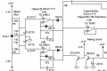
The 45 year old circuit used 3 zener diodes 3 pnp transistors and 1 npn transistor in it's clipping circuit. It ran from a dual voltage supply. Anyhow my research on voltage clipping circuits has left me a bit lost and I can not make heads or tails of the original circuit. Anyhow the project is to make this work with analog, not a digital control replacement.

Does anyone know of a good example of a high low clipping circuit that can work in the voltage range mentioned?
 

#12

Joined Nov 30, 2010
18,224
A window comparator will detect 2 different voltage events so you can process them as needed but a schematic of the original circuit would help a lot. Most of us have spent decades figuring out somebody else's circuits. This seems simple, but how to apply it depends entirely on what you have to start with.
 

DickCappels

Joined Aug 21, 2008
10,661
I think your best bet is to restore the original circuit.

The clipping circuit below was designed to clip pink noise and it works very well. It can be adapted to your voltages. The input is through the 10k resistor and the input swings symmetrically about ground. The output is taken at the output of U3B.

upload_2017-1-17_12-5-22.png
 

AlbertHall

Joined Jun 4, 2014
12,637
For clarity, the input is the 10k resistor at the top of the circuit. I spent a while trying to see how this would work with the input through the 10k at the bottom right of the circuit.
 

Thread Starter

Desertland

Joined Jan 16, 2017
8
I think your best bet is to restore the original circuit.

The clipping circuit below was designed to clip pink noise and it works very well. It can be adapted to your voltages. The input is through the 10k resistor and the input swings symmetrically about ground. The output is taken at the output of U3B.

Thanks for posting the circuit, have a question on the voltage. I see - 12 and + 12. is this a dual voltage circuit? or single supply?
 
Last edited by a moderator:

DickCappels

Joined Aug 21, 2008
10,661
I rotated your drawing to make it easier to read.

There are thee power inputs to the circuit: +12V, Ground, and -12. Ground is common to both supplies. (Thanks to AK for catching an error introduced by editing).

Out of curiosity, what patent did this come from?
 
Last edited:

AnalogKid

Joined Aug 1, 2013
12,221
Coming up with a dual comparator circuit that does things at two different trip points is common stuff. But it won't replicate the "knee", the clipping circuit characteristics as the clipper goes from not clipping to clipping as the sensor voltage transitions its clip levels. The simplest way to have the same transition region characteristics is to replicate the original circuit. If it ain't broke ...

Are any of the transistors or diodes in the original circuit Germanium?

ak
 

Thread Starter

Desertland

Joined Jan 16, 2017
8
. The simplest way to have the same transition region characteristics is to replicate the original circuit. If it ain't broke ...

Are any of the transistors or diodes in the original circuit Germanium?

ak
The diodes are zener. As for the transistors I would have to look up each of them to know. It used 2N 3903, 3905, 3638 and 1309.
Your right ak .. if it ain't broke. What I'm not sure about how to deal with ( it may be simple and it is only complicated in my mind ) is that the sensors used in the 45 year old version used variable resistance. If a new version of this is built it would have to run from sensors that output a variable voltage. Does this have any implications on the circuit design?
 

Alec_t

Joined Sep 17, 2013
15,145
The modern sensor produces a very small voltage from about 20mv to 200mv. Using a 10 to 1 gain via a 741 op amp the signal from each sensor is sent to both a meter calibrated in the 0 to 3 volt range and then to a voltage clipping circuit.
A 741 can't handle inputs closer than about 2-3V to either supply rail, so is unsuitable unless you have a dual polarity supply. There are much better opamps available. Even the humble LM324 could handle the voltage range (although its bandwidth isn't great).
 

AnalogKid

Joined Aug 1, 2013
12,221
Right now i used the 741 with a single supply.
That won't work. A 741 is old. That in and of itself is not a problem, but it does mean that it is the ultimate NON-rail-to-rail opamp. Neither the input common mode (signal) range nor the output voltage swing range gets within 2 or 3 volts of either rail (working from memory; check the datasheet). If bipolar power is not available,e then move to a part that meets your input and output requirements. I suggest starting with an LM358 and moving on from there if it is inadequate.

BTW, another factor is accuracy. Those older parts have relatively large input offset voltage and input bias current errors, and with a DC gain circuit those errors pile up fast. data-data-datasheeet.

ak
 

Thread Starter

Desertland

Joined Jan 16, 2017
8
That won't work. A 741 is old. That in and of itself is not a problem, but it does mean that it is the ultimate NON-rail-to-rail opamp. Neither the input common mode (signal) range nor the output voltage swing range gets within 2 or 3 volts of either rail (working from memory; check the datasheet). If bipolar power is not available,e then move to a part that meets your input and output requirements. I suggest starting with an LM358 and moving on from there if it is inadequate.

BTW, another factor is accuracy. Those older parts have relatively large input offset voltage and input bias current errors, and with a DC gain circuit those errors pile up fast. data-data-datasheeet.

ak
A 741 can't handle inputs closer than about 2-3V to either supply rail, so is unsuitable unless you have a dual polarity supply. There are much better opamps available. Even the humble LM324 could handle the voltage range (although its bandwidth isn't great).
OK.. Thanks to both of you. I'm going to take your input on the op amp. As far as accuracy goes if running this from a bipolar power is the best option then that is what I'll do. Am going to try and get an updated circuit drawn out later today. Again, thanks for the input.
 

Thread Starter

Desertland

Joined Jan 16, 2017
8
Coming up with a dual comparator circuit that does things at two different trip points is common stuff. But it won't replicate the "knee", the clipping circuit characteristics as the clipper goes from not clipping to clipping as the sensor voltage transitions its clip levels. The simplest way to have the same transition region characteristics is to replicate the original circuit. If it ain't broke ...

Are any of the transistors or diodes in the original circuit Germanium?

ak
After doing a bit of searching specs the 1309 is a germanium , the others are silicone.
The 3903 and 3905 are listed in the Digi key catalog. The Germanium 1309 and silicone 3638 I think I need to find a close equivalent for.
 
Last edited:

Thread Starter

Desertland

Joined Jan 16, 2017
8
OK.. thanks. I'll give the circuit a closer look.
Not all of them. part 250 in series with a transistor emitter is shown as a signal diode. The 0.4 V difference between Ge and Si could have a very real effect on circuit function.

ak
Signal diode 250 is inside a dotted box. At first I thought that was just an internal view of op amp 226 and 227. Now I see that 226 and 227 represent everything inside the dotted box .. Thanks for noticing that. That detail had not registered with me.
 

AnalogKid

Joined Aug 1, 2013
12,221
It is common in industrial equipment schematics with multiple identical circuits to draw one in detail and the rest as boxes with inputs and outputs. It also is common in patent documents, which your drawing is similar to in some ways.

ak
 
Last edited:
Top