 Facebook
 Google
 GitHub
 Linkedin
Hi folks, looking for help fixing the charger - it's not about the money at this point, but understanding why
The closest similar schematic I found is for the 115(4A) version, mine is 112 (2A)
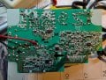
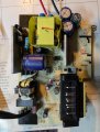
I marked all parts replaced in red
Other pics are the actual PCB
I dug through the entire high-voltage part - from diodes and power field effect transistor to Zener diodes, resistors and optocouplers... individually all the parts are intact (I unsoldered and checked and back), but the PWM iw1710-01 doesn't start. 8...10 volts appear on the power supply (it constantly oscillating in this range, the same voltage on pin 3 (Vin). The Zener diode and transistor, the capacitor through which V goes to pin 8 have been checked - everything is intact.
I replaced the PWM with a new one - still same, it does not start. Something "holds" the start. What? I have run out of thoughts ... what else to check? Yes, if you cut off the low-voltage part immediately after the transformer , and supply 24V there from another power supply - charging works, blinks, charges .. everything is fine on the low side .....
What "holds" the PWM from starting?
EDIT: One more thing I discovered is that when using the 24V bench power supply on the charger part the optocouplers PC1 and 2 (3 is not present in the DBC112 version) have 0.98V on the LED. When I reconnect the charger to 120V (the bench 24V power supply not connected) it starts charging and stops after 2 or 3 blinks. After that the PC1 has 1.2V on the LED and PC2 only 0.2V so I presume it disables the power supply controller chip ? But why?
Can someone please help me to understand why is PC2 disabling the charging? (I presume that is the case)
Thanks!
The closest similar schematic I found is for the 115(4A) version, mine is 112 (2A)
I marked all parts replaced in red
Other pics are the actual PCB
I dug through the entire high-voltage part - from diodes and power field effect transistor to Zener diodes, resistors and optocouplers... individually all the parts are intact (I unsoldered and checked and back), but the PWM iw1710-01 doesn't start. 8...10 volts appear on the power supply (it constantly oscillating in this range, the same voltage on pin 3 (Vin). The Zener diode and transistor, the capacitor through which V goes to pin 8 have been checked - everything is intact.
I replaced the PWM with a new one - still same, it does not start. Something "holds" the start. What? I have run out of thoughts ... what else to check? Yes, if you cut off the low-voltage part immediately after the transformer , and supply 24V there from another power supply - charging works, blinks, charges .. everything is fine on the low side .....
What "holds" the PWM from starting?
EDIT: One more thing I discovered is that when using the 24V bench power supply on the charger part the optocouplers PC1 and 2 (3 is not present in the DBC112 version) have 0.98V on the LED. When I reconnect the charger to 120V (the bench 24V power supply not connected) it starts charging and stops after 2 or 3 blinks. After that the PC1 has 1.2V on the LED and PC2 only 0.2V so I presume it disables the power supply controller chip ? But why?
Can someone please help me to understand why is PC2 disabling the charging? (I presume that is the case)
Thanks!
Attachments
-
3 MB Views: 19
-
 429.9 KB Views: 21
 -
 167.4 KB Views: 20


