Attempting to drive two devices with PIR

Thread Starter

Brianaala

Joined Feb 15, 2019
62
Hi folks,
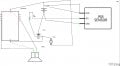
I'm relatively new to creating circuits. I'm trying to drive a very low current (~27mA) Mp3 module and a small DC motor from a PIR running through a TIP31c transistor. The entire circuit is powered from a 5v 2A PC power supply. The PIR outputs 3.3v to switch the base of the TIP31c through a 1K resistor with 5v to the collector. It will power the MP3 but when I attach the motor nothing seems to power up. The DC motor runs on 5v and pulls less than 1A so the TIP31c can easily handle that, however the same circuit with the MP3 removed (trying to run just the motor with the TIP31c and PIR) does not work either...so clearly the addition of the motor is the issue but I'm not sure why, could it be from voltage drop?
 

Attachments

wayneh

Joined Sep 9, 2010
17,496
Does the motor run OK on 5V all by itself? What is the voltage of your 5V source in the diagram, when the motor is attached directly to it?
 

Thread Starter

Brianaala

Joined Feb 15, 2019
62
Hi Wayneh!
It does run fine with the PS directly attached. I'm not sure what you mean by the voltage of my 5v source... my DVM is reading ~5vdc when the motor is connected directly.
 

wayneh

Joined Sep 9, 2010
17,496
Hi Wayneh!
It does run fine with the PS directly attached. I'm not sure what you mean by the voltage of my 5v source... my DVM is reading ~5vdc when the motor is connected directly.
OK, that's what I meant. I just wanted to be sure the power supply actually has enough power to drive the motor. Sounds like it does.

So now I wonder about the TIP31c. It doesn't seem to be passing enough current to satisfy the motor. A Darlington is two transistors, and so the rule-of-thumb for reliable switching is that you need a base current of 1/100th of the load current. Each individual transistor requires a 10X factor and together that multiplies to a 100X factor. Also, the base-emitter voltage doubles for a Darlington, meaning your base voltage will be ~1.4V when it's conducting.

Suppose the motor needs 175mA to get started. I have no idea if that's true, but it's a reasonable number. Combined with your player's 25mA draw, your combined load is 200mA. So your Darlington should be able to switch that with just 2mA of base current. The signal coming from the PIR is 3.3V? That means the base resistor should drop no more than 1.9V (PIR 3.3V minus base 1.4V) at 2mA. Applying Ohm's law ∆V = I•R: 1.9V = 0.002A • R and therefore R ≤ 1.9V/0.002A = 950Ω. Your 1000Ω resistor "should" be OK in this scenario and I'm a little surprised it's not working. It makes me think the motor may be looking for more current than the 175mA I've guesstimated.
 

Thread Starter

Brianaala

Joined Feb 15, 2019
62
Aha! I suspect you're absolutely correct Wayneh! I think the motor is drawing much more than that; it's turning a gear mechanism, so I suspect the current load is much higher than that. Perhaps I could run a relay to the motor instead... maybe a 5v relay and set up both the mp3 and the motor in parallel from that? Thank you so much for your help!
 

Thread Starter

Brianaala

Joined Feb 15, 2019
62
Hi Alec,
Yeah I made the diagram with Fritzing and I didn't have an actual TIP31c (that I could find) so I used a MOSFET in it's place. But yes the actual TIP31c is correctly connected.
 

wayneh

Joined Sep 9, 2010
17,496
Aha! I suspect you're absolutely correct Wayneh! I think the motor is drawing much more than that; it's turning a gear mechanism, so I suspect the current load is much higher than that. Perhaps I could run a relay to the motor instead... maybe a 5v relay and set up both the mp3 and the motor in parallel from that? Thank you so much for your help!
Personally, I would use a logic level MOSFET rated to >4X whatever amperage your motor draws when running. Why 4X? It's good to have a safety factor of 2X all the time and I'm assuming your motor draws twice as much current in the instant it starts up or is heavily loaded. And adding current to a MOSFET specification adds little to its cost, so why not?

A MOSFET is superior to a Darlington because it requires virtually zero base (actually, gate) current to turn on. The negative is that the gate voltage needs to be higher. Your 3.3V could be borderline but I think it would be fine.

No matter you choose, you need to know the current demand of your motor. Start with measuring that.
 

Thread Starter

Brianaala

Joined Feb 15, 2019
62
OK, thanks Wayneh!! I will measure the current pull from the motor when I get home. I didn't think the PIR could operate a MOSFET...I figured that the transformer was my only option besides a relay.
 

Thread Starter

Brianaala

Joined Feb 15, 2019
62
Oh, ok I'll try to take it down to 220 and see if that has any effect. I can't get around to it until tomorrow afternoon though. Thank you so much Wayneh!
 

Thread Starter

Brianaala

Joined Feb 15, 2019
62
Hi Wayneh,
Well I reduced the resistor to a 220 and it still won't drive the motor. I thought that the TIP31c could drive the motor, but to be honest I haven't even figured out how the prop is going to work yet anyway, so maybe I need to try my hand at a MOSFET like you suggested. I'm not sure if the PIR can run a MOSFET; does it make a difference on the size of the MOSFET? You mentioned to get one that is 4X the current capability that I need, would that preclude the 3.3v PIR signal from activating it? The PIR has a very low current output (which is kind of why I'm struggling to get this thing to run).
 

wayneh

Joined Sep 9, 2010
17,496
The MOSFET will help! It needs only a voltage and almost no current. But you need to know what current the motor requires, and you need a logic level MOSFET. A plain vanilla MOSFET requires about 10V to fully turn on, and that won’t work for you.
 

wayneh

Joined Sep 9, 2010
17,496
Thanks Wayneh! Forgive my ignorance but what is a logic level MOSFET ?
It’s simply a MOSFET, a type of transistor, that will turn fully on with a relatively low gate voltage. A regular MOSFET is usually fully on at 10V or so. A logic level one is fully on at 5V or less. I don’t know if any of them are fully on at 3.3 V, but the on resistance will be low enough to handle the motor current.
 

Thread Starter

Brianaala

Joined Feb 15, 2019
62
Awesome! I know that these things have fairly (to me anyway) cryptic codes. Is there a number I should look for or will any Logic level MOSFET do?
 

wayneh

Joined Sep 9, 2010
17,496
Awesome! I know that these things have fairly (to me anyway) cryptic codes. Is there a number I should look for or will any Logic level MOSFET do?
Well again, the two critical specs are the current rating which is dictated by the motor’s needs, and the logic level requirement dictated by your PIR output. Other than those two things, just about any N-channel MOSFET would work. We can help you find one but not without the motor data or specs.
 
Top