 Facebook
 Google
 GitHub
 Linkedin
I don't know! :-/The multimeter should be set to DC Volts, not AC. The range should be the next higher one than 24.
Do you know how to measure current?
When I did DC nothing seemed to happen! No stable numbers, zeroes or minuses.
Even with no wire pot is still sparking and smelling of burn. Should I just give up on this power source and find another?
PS shiny new multimeter now! Pic attached. I used the first setting from the left.
Attachments
-
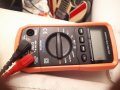 4.3 MB Views: 2


