Facebook
 Google
 GitHub
 Linkedin
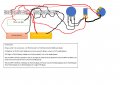
Red ledberg doesn't go to the pot. The wires have followed the schematic on post #134 page 7 so would need to know where the converter goes in relation.If the white one is also an LED strip rated for 12V, it should also have a converter. But, if you wire the red wires from both strips to the yellow wire and the black wires from both strips to the black wire, one converter will work.
The catch is that you are dimming the red strip with the pot and transistor. So instead of running the yellow wire to the red strip, it should go to the pot... where the red wire of the Ledberg goes now.
I’ll try to sketch it, but won’t be able to do so right away. If you put the converter between the Ledberg and it’s connections (to the terminal block?) it should work.
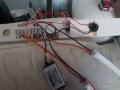
I assume that doubling the wires to the converter doesn't double the load?
")