ATMega2560 to FTDI to PC

Thread Starter

BlackSolis

Joined Jan 26, 2022
11
Hi

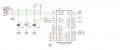
I have an ATMega2560 16U-IH chip connected to an FT232RL FTDI chip which is then connected to my PC. From the PC, I am able to see the FTDI chip but unable to communicate with the ATMega2560 chip.

The wiring:

PC (USB) -> FTDI chip: - see attached image
+5v (red USB wire) to Pin 20 (VCC). Also a 0.1uf non-polarised capacitor to GND and 10uf polarised capacitor to GND
GND (black USB wire) to Pin 7, 18, 21, 25 & 26 (GND)
D+ (green USB wire) to Pin 15 (USBDP)
D- (white usb wire) to Pin 16 (USBDM)

FTDI chip to ATMega2560 chip - see attached image
Pin 1 (TXO) to Pin 2 (PE0)
Pin 5 (RXD) to Pin 3 (PE1)

ftdi wiring
ftdi wiring999×410 57.7 KB


The ATMega2560 is also powered from the USB +5v and GND (power is getting to the ATMega2560 chip).

Is there anything I am missing here that would stop this from working?
 

Attachments

DickCappels

Joined Aug 21, 2008
10,153
Double-check the RXD and TXD connections.
Did you successfully install the FTDI driver?
How are you trying to interact with the FTDI device (For example, terminal simulator)?

Picky stuff: C1 is 10x larger than recommended in the datasheet, probably ok.

Same possible issue with the power supply bypass capacitors and the absence of a ferrite bead.
1643204073413.png
Has the internal EEPROM been programmed?
 

MrChips

Joined Oct 2, 2009
30,707
Depends on what you mean by communicate with ATmega2560 chip.
In order to communicate you need software running on the ATmega2560 chip.
 

Thread Starter

BlackSolis

Joined Jan 26, 2022
11
@DickCappels
I have installed the FTDI driver and I can see it under Ports in Device Manager (Windows) and ttyUSB0 in Linux.
I am (trying to) communicating with the ATMega2560 chip via the FTDI via serial in a program I've written in C. I can successfully connect to and communicate with an Arduino Mega (uses the same ATMega2560 chip) using my program and a program uploaded to the Arduino.
The ATMega2560 chip I am trying to communicate with has this same program burned to it.

Thanks for the picky advice :cool: , I am new to the hardware stuff!
 

Thread Starter

BlackSolis

Joined Jan 26, 2022
11
Does that mean that you are not succeeding in getting the bootloader to recognize the AVR controller?
The ATMega2560 chip has a bootloader and software on it already, I can communicate with the chip when it is on an 'Arduino Mega' board but not when I put it on my own PCB with the FTDI chip.
I also tried a CH340 instead of the FTDI but I have the same problem o_O
 

DickCappels

Joined Aug 21, 2008
10,153
Looks like we don't know whether the problem is in the protocol, the usb-to-serial converter or the 'Mega2650.

Do you have a terminal emulator? If not you should be able to find one easily, there might already be one in you Linux package. If you can, fire up the terminal, open the emulator and software wise connect it to the USB-to-Serial adapter (FTDI chip) with local echo off. Then connect TXD and RXD on the FTDI chip to one-another and nothing else. If the FTDI chip is working it will echo back characters typed into the terminal. A further test is to disconnect TXD from RXD which should stop the echoing of characters. That will tell us something about where to look next.
 

Thread Starter

BlackSolis

Joined Jan 26, 2022
11
Thanks @DickCappels and others.

I ended up reconfiguring the PCB but now have a slightly different problem...

I have a custom PCB which has an ATMega2560 and FTDI32RL.
I have burned a bootloader to the ATMega2560 using Nick Gammon's bootloader and I am able to successfully upload sketches to the ATMega2560 from the Arduino IDE. The PC can also see the PCB via device manager / tty.

My issue is that when I run the same sketch on a genuine Arduino Mega with the same (replicated) wiring, the LCD, keypad, serial and i2c communications all work very well. When I run the sketch on my custom PCB, the serial and i2c should echo back what I send but are intermittent (sometimes works OK, sometimes the message received back is incorrect or sometimes missing altogether), the LCD does not work (only powers up with blocks on the top row and the keypad does not work (this may be linked to the serial). All +5v on the board comes from a single USB pin and all GND comes from a single USB pin (i.e. all the VCC are linked and all GND are linked).

My initial thoughts are there is some interference to cause the serial to be unreliable but I am unsure why the LCD would not work. I have checked all pins for continuity and they are all OK.

**Connections:**

**Power -> ATMega2560**
+5v -> VCC (0.1uf capacitor to GND)

**FTDI -> ATMega2560**
1 (TX) -> 2 (RX)
2 (DTR) -> 30 (RESET) via 0.1uF capacitor & pulled high by10k resistor
5 (RX)-> 3 (TX)
15 (D+) -> PC (USB)
16 (D-) -> PC (USB)
4, 20 -> +5v (0.1uf and 10uf capacitors to GND)
7, 18, 21, 25, 26 -> GND

**LCD -> ATMega2560**
1|GND
2|+5V
3|GND
4|6 (PE4) – RS
5|GND
6|8 (PE6) – EN/ES
7|13 (PH1) – DB0
8|12 (PH0) – DB1
9|15 (PH3) – DB2
10|14 (PH2) – DB3
11|17 (PH5) – DB4
12|16 (PH4) – DB5
13|19 (PB0) – DB6
14|18 (PH6) – DB7
15|+5V
16|GND

**Keypad -> ATMega2560**
1|24 (PB5)
2|26 (PB7)
3|28 (PG3)
4|25 (PD2)
5|36 (PL1)
6|38 (PL3)
7|40 (PL5)
8|42 (PL7)
9|46 (PD3)
10|27 (PH7)
11|29 (PG4)
12|35 (PL0)
13|37 (PL2)
14|39 (PL4)
15|41 (PL6)
16|47 (PD4)

If anyone could shed some light on this or advise things to try I would be greatly appreciated.

BS
 

LesJones

Joined Jan 8, 2017
4,174
Do you have the 1K resistors fitted between the Rx/Tx connections between the ATmega and the FT232RL ? Without them there may be a situation when the Rx and Tx pins are configured as digital outputs when the FT232RL is trying to send data to the ATmega. I can't remember the details but I think I have seen a situation on a arduino uno where these resistors are required.

Les.
 

DickCappels

Joined Aug 21, 2008
10,153
I've been using ATMEGA controllers since they first came out and those resistors were never required. I do as a matter of precaution make sure the TXD pin is set as an output and the RXD pin is set as an input in the appropriate DDR (Data Direction Register).
 

Thread Starter

BlackSolis

Joined Jan 26, 2022
11
Do you have the 1K resistors fitted between the Rx/Tx connections between the ATmega and the FT232RL ? Without them there may be a situation when the Rx and Tx pins are configured as digital outputs when the FT232RL is trying to send data to the ATmega. I can't remember the details but I think I have seen a situation on a arduino uno where these resistors are required.

Les.
Thanks Les.
I haven't got 1k resistors in place on the RX/TX lines between the ATMega2560 and FTDI chip.

I've been using ATMEGA controllers since they first came out and those resistors were never required. I do as a matter of precaution make sure the TXD pin is set as an output and the RXD pin is set as an input in the appropriate DDR (Data Direction Register).
Thanks DickCappels

I tried setting the RX & TX pins:
DDRB = (0<<PE0); // Pin 2 (RX) INPUT
DDRB = (1<<PE1); // Pin 3 (TX) OUTPUT


It seems now (if it indeed changed) that if I send commands about 1-2 seconds apart, most of the time I get the correct response back but still occasionally the response is missing some characters. Another strange thing is, when I do receive part of the string, I always seem to receive the last character (they all end in a '%').
If I send the commands quickly, a lot of them are missed.

Update:
I ran this sketch:

Code:
int a = 0;

void setup() {
// put your setup code here, to run once:
DDRB = (0<<PE0); // Pin 2 (RX) INPUT
DDRB = (1<<PE1); // Pin 3 (TX) OUTPUT

Serial.begin(115200);
while (!Serial) ; // wait for serial port to connect. Needed for native USB
}

void loop() {
  // put your main code here, to run repeatedly:
delay (1000);
Serial.println(a);
a++;
}
The serial monitor received every number with no problems.

I changed the delay (1000); value from 1000 to 100 then 10 then 1 and it worked fine too.

Because of this I'm now thinking maybe my chips crystal or something isn't quite right and my code isn't actually being executed correctly?

The crystal I am using is the 16.00 mhz variant of this
1645009418319.png

https://www.aliexpress.com/item/4000148902931.html?spm=a2g0o.order_list.0.0.21ef1802n5yZu8

and I have it wired like this:

1645009224577.png

Thanks
BS
 

DickCappels

Joined Aug 21, 2008
10,153
1645024923782.png

You can get by without the capacitors but then you're likely to have unreliable operation.

Also make sure you have the relevant fuses set correctly.
 

Thread Starter

BlackSolis

Joined Jan 26, 2022
11
You should have the crystal wired with 2 x 22pF capacitors, not a 1M resistor.
https://forum.arduino.cc/t/16mhz-crystal-selection-for-atmega328p/609377
I have incorporated 2x 22pF capacitors as per that post (and removed the resistors), unfortunately I still have the same issue.

View attachment 260805

You can get by without the capacitors but then you're likely to have unreliable operation.

Also make sure you have the relevant fuses set correctly.
Thanks, I have incorporated 2 x 22pF capacitors (and removed the resistors) but I still have the same issue.

I re-uploaded the bootloader to check and then I uploaded the bootloader I am using (Nick Gammon's bootloader) to an Arduino Mega board and ran the same code and it works perfect so I think the fuses would be set OK, unless there is something else to check with the fuses?

Thanks
BS
 
Top