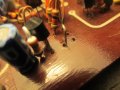
Are these 2 transistors close enough?

Reloadron

Joined Jan 15, 2015
7,921
Yeah I sure do agree!. I should have mentioned earlier that this motor controller worked perfectly fine before then it shorted out on it's own chassis and popped a transistor when I plugged it in. All because I didn't bother to put in all the screws for a test. Then I blew out 2 more transistors while messing with it. But the good news is I've studied all the paths of the circuit and think I know how it works now. There is that main transistor we talked about, a little transistor that bleeds off voltage from its base and 2 other transistors that bleed off voltage from the same base in 2 stages. So it's all about taking away voltage and not adding to it. I should ignore all capacitors in the circuit because they just prevent electrical noise don't they?
Without actually looking at a circuit diagram it's really hard to say exactly what components do what. Capacitors in general can perform several functions, such as filters or coupling to name a few. Simply put a capacitor will block DC and pass AC, a capacitor opposes a voltage change where an inductor will oppose a current change. That being very over simplified.

Your output transistor(s) drive the output but the smaller transistors which precede them are likely driver transistors. The terms "bleed" or "bleeder" is not likely the best choice of words to describe them.Bleed or bleeder usually imply for example bleeding off current such as using a bleeder resistor in a power supply to bleed off current or voltage from capacitors like filter capacitors when mains power is removed (turned off). Really more about how terminology is applied and used. Keep in mind, as Tony has stressed, a transistor is basically a current device and in this case a "darlington" transistor is just two transistors on a single die (in a single package) and the merit to this configuration is the ability to handle more current. :)

<EDIT> As I slowly typed I see Tony added more worthwhile information. :) </EDIT>

Ron
 

Thread Starter

slashmaster2

Joined Apr 15, 2019
17
Thanks Ron! Thanks Tony! I'm going to try to draw out a diagram of the circuit later. I think I'll also try removing one of the transistors out of circuit and see what happens to the voltage. I do not own a multimeter that has a place where you can plug in a transistor to test. Is a multimeter like that worth having? Or is the diode function of a regular multimeter good enough to test a transistor? By the way Tony, the whole system for the motor is 28 volts and same bridge rectifier for motor also runs electronics. Motor runs good and at full speed when I run jumper from base of that Darlington transistor to positive. At the bridge rectifier I'm getting a few more dc volts than ac volts so that probably indicates the big filter capacitor is good doesn't it?
 
Last edited:

Tonyr1084

Joined Sep 24, 2015
9,744
It's always difficult to diagnose someone else's circuit without being able to put hands on it. However, the higher DC voltage IS expected because the filter cap is capturing the peak voltage from the sine wave. In AC, the peaks of the waves are pretty much useless. A 10 volt transformer (for instance) has an RMS value of 10 meaning its peak wave is actually 14.14 volts (any AC voltage can be multiplied by 1.414 to get the peak voltage). When rectified and filtered, you'll get close to that peak voltage. The reason why you don't get the full thing is because going through a diode typically drops the voltage by (typically) 0.7 volts. When using a bridge rectifier you're going through two (of four) diodes at any given time, so you'll typically drop 1.4 volts

As for using a multimeter to check transistors, I typically use the diode function. On an NPN transistor you should see a reading, depending on the transistor, one way but not the other. I'd specify but I'd have to run to my lab to test one just to have the correct answer. It's something I seldom have had to do. Nevertheless, between the N and the P (NP of the NPN) you should get a reading one way but not the other. And between the P and the N (the PN of the NPN) you should get a reading - again - one way but not the other. This isn't the best way to tell, but should work well enough to determine if you have a shorted or open transistor. I don't recall, but you might get a reading between the two N's, but again, I'm not sure. I'm sure if I'm wrong someone will correct me on that.

CAUTION: When driving the base directly from full power (without going through a resistor) you're running the risk of damaging the transistor. Also, I wouldn't count fully on that to determine the rectifiers are doing their job. They probably are, but you can't rule that out completely. But for what it's worth, it sounds like your supply and the rectifiers are doing their job.

As for the filter cap - yes, it stands to reason it's good. However, one question remains; why did the first darlington transistor blow out? Did you overload the motor? Did you stall the motor? Was there an intermittent short? Did Back EMF (BEMF) cause the diode to fail? BEMF is something you should take a look at. Basically a snubber diode across the motor leads will snub any backlash from the motor. I'm not good at explaining BEMF so I won't even try. All I WILL say is that a diode with the cathode connected to the positive side of the motor and the anode to the negative side should protect the transistor.

You mention having other transistors in the circuit. There's a possible fault there as well, but without hands on OR a good diagram of the circuit it's pretty hard (at least for me) to envision how your circuit is designed to operate.

Do you want the motor to run at full speed when on? Or are you trying to control the speed? Those answers are also critical in understanding how your circuit is working. Please answer if you can.
 

ian field

Joined Oct 27, 2012
6,536
Trying to replace this blown transistor from a dc motor speed controller. Looks like you can see the bulge of where it puffed up when it blew. Is my new replacement close enough?
AFAIK: Both transistors have the Toshiba logo - the one on the right is just more recent.

Should be OK - but the counterfeiters have got very professional. Fake parts have once or twice found their way into the inventory of trusted suppliers. Fake semiconductors are less jail time than running drugs.
 

Thread Starter

slashmaster2

Joined Apr 15, 2019
17
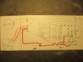
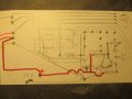
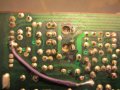
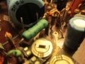
Ok, I made a schematic but it's not really finished yet. I found I could get it to work by removing one of the transistors and a resistor that takes power away from the base of that main Darwin transistor. On the schematic I tried to imitate the same basic arrangement as on back of the board. Hope you guys understand it. Was it a good move when I highlighted in red everything that is full voltage? I was thinking about highlighting other voltages in a different color. Did I make the right symbol for the 2 little trim pots? These are pots you can only access by taking the cover off the projector, not normal controls. Oh yeah, to the top right is just a reverser switch and below that is the 2 speed selector switch. The last pic is where I unsoldered one of the transistors and one end of a resistor and got it to work but it doesn't give you more power under load the way it use to.
 

Attachments

Ylli

Joined Nov 13, 2015
1,092
I see only one other transistor in the schematics you posted. Sounds like you have that smaller transistor removed from the circuit. Use your ohmmeter on the diode range to check the junctions in that smaller transistor.
B-E: open one direction, about 0.6 volts other direction.
B-C: open one direction, about 0.6 volts other direction.
C-E: Open both directions.
 
Top