Arduino regulation High voltage >= 100 kV

Status
Not open for further replies.

MisterBill2

Joined Jan 23, 2018
27,980
CRT power supplies have a limited current. The larger ones I made have a good current limit. 40kv is the highest I made for CRTs.
Now that I think about, I remember an x-ray machine at 110kv. I don't remember the current, but it must have been high.
I worked broadcast transmitters for 6 years. The main supply was 6kv to 10kv but the power limit was 35kWatts. That is impressive when it gets out of control.
I worry when I see youtubes of kids playing with neon sign transformers.
I also had a 12,000 volt neon sign transformer when I was in grade school. I did a lot of interesting experiments with the high voltage. BUT I never ever "Played around with it". I never got shocked, either. And most of that was without any parental supervision. So the question I have is how does one define playing around versus careful experimenting???
 
The difference between playing around and experimenting is whether or not you document your setup and results. Play around all you want, and if you don't document it, it's as if it never happened. Properly document playing around, and all of a sudden you have data to publish for possible grants.
 

MisterBill2

Joined Jan 23, 2018
27,980
The difference between playing around and experimenting is whether or not you document your setup and results. Play around all you want, and if you don't document it, it's as if it never happened. Properly document playing around, and all of a sudden you have data to publish for possible grants.
OK, it is clear that you have an entirely different mindset from those who experiment exclusively for their own education and experience. That is appropriate in both the educational research realms and in industry.
I, and many others have the great benefit of not having to prove anything to anybody. BUT we are not "playing around", but rather educating ourselves for our own benefit. And I am not in the business of applying for research grants.
 
Last edited:

panic mode

Joined Oct 10, 2011
5,162
nothing from TS....

the title says not just monitor (measure) but also control or regulate 130kV voltage.
and that's it... it does not even say if this is AC or DC.

for any closed loop system feedback is needed (measuring). this can be done with help of suitable voltage divider. controlling or regulating that voltage would be the next step assuming one knows the way that voltage is generated.
 

MisterBill2

Joined Jan 23, 2018
27,980
nothing from TS....

the title says not just monitor (measure) but also control or regulate 130kV voltage.
and that's it... it does not even say if this is AC or DC.

for any closed loop system feedback is needed (measuring). this can be done with help of suitable voltage divider. controlling or regulating that voltage would be the next step assuming one knows the way that voltage is generated.
A major requirement for the elements of that feedback system is both stability and accuracy.
 

Thread Starter

amn.hassan

Joined Nov 14, 2024
7
First so sorry for the delay. I was out for 3 weeks.
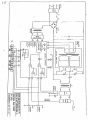
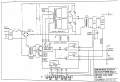
My cooleages My colleagues I'm arrived home. So I need to control a DC HV = 130 KV power supply with Arduino Mega. I mean to : to switch on/off, increase and or decrease KV. The power supply is a commercial unit. It has the following circuit for remoting and triggering if i understand well:
1734277680191.png1734277680191.png
So If some one can help me it will be kind.
 

Thread Starter

amn.hassan

Joined Nov 14, 2024
7
nothing from TS....

the title says not just monitor (measure) but also control or regulate 130kV voltage.
and that's it... it does not even say if this is AC or DC.

for any closed loop system feedback is needed (measuring). this can be done with help of suitable voltage divider. controlling or regulating that voltage would be the next step assuming one knows the way that voltage is generated.
It s DDC current, and Maximum 50 mA
 

MisterBill2

Joined Jan 23, 2018
27,980
OK, now we have a partial schematic of part of the circuit, which shows terminals for voltage programming and current programming, both of which appear to be portions of feedback circuits where either an isolated voltage source could be applied, or possibly where an isolated resistance could be inserted. I also see current feedback and voltage feedback terminals. So the connections are there and the controls are totally analog. And we have no clue as to what the signals are.
 

DickCappels

Joined Aug 21, 2008
10,662
What instruments to you with which to measure the output voltage?

The output of your diode bridge is connected backwards. The positive output should go to the collectors of Q1 and Q2. The connection of the negative output is left as an exercise for the student.
 

MisterBill2

Joined Jan 23, 2018
27,980
In the schematic portion I see analog meters for measuring, as well as scaled output terminals. So it would appear that analog inputs to an A/D converter of some range and scale will work for monitoring. Controlling the outputs will not be so simple because what is shown looks like output programming connections, which are not at all the same as output control inputs. Rather, those "Programming" connections appear to be for adjusting the feedback circuits operation. Not at all the same, and not so simple.
 

panic mode

Joined Oct 10, 2011
5,162
i see no problem... looks like classic SMPS... the "control assembly" also shows everything one sees in just about every SMPS.

the two potentiometers are not for calibration of the analog gauges. They tie back into PWM circuit.

Current control sets current limit of the output
Voltage control is exactly what you want. IT allows you to set (program) desired output voltage.

and as a bonus, everything needed is already on TB1... including voltage feedback, voltage control and the reference... one could not ask for more.

measure REF , change voltage using voltage control potentiometer while measuring voltage mon.... and you are half way there.
 
Last edited:

MisterBill2

Joined Jan 23, 2018
27,980
OK, It appears like control will require having information that is not provided to us. It might be simple, or it might not be quite so simple.
What is immediately obvious is that the arduino analog I/O will need to be isolated from other common circuits. That might be a challenge. And still no clues about "v-ref", nor the monitor output voltage range or scale factor.
 

Thread Starter

amn.hassan

Joined Nov 14, 2024
7
What instruments to you with which to measure the output voltage?

The output of your diode bridge is connected backwards. The positive output should go to the collectors of Q1 and Q2. The connection of the negative output is left as an exercise for the student.
The out put voltage is measured by an analogue panel meter
 

MisterBill2

Joined Jan 23, 2018
27,980
Since that drawing contains at least one very obvious error with the diode bridge polarity, the entire drawing is suspect as far as accuracy goes. It claims, in the title block, to be a block diagram, while it contains some rectangles without much definition, it does not pass my evaluation as a useful block diagram. There is way to much needed information missing.
 

panic mode

Joined Oct 10, 2011
5,162
agreed...
meanwhile can some measurements be done to confirm REF voltage, range of output and Voltage Monitor terminal when turning Voltage Control? what does INTERLOCK function do?
1734390931278.png
 

DickCappels

Joined Aug 21, 2008
10,662
"The out put voltage is measured by an analogue panel meter"

And how will the Arduino be able to read the voltage? Do you have a high voltage divider that can handle >100 KV?

What training or experience have you had at voltages like this?
 

panic mode

Joined Oct 10, 2011
5,162
i'd dare a guess that he is totally inexperienced... if he knew more, he would have already answered the questions.

the way i see it, block "filter feedback" contains the necessary HV voltage divider. so scaled down low voltage goes back to "control assembly" where it is used to control the PWM through U4/U5, drive dial gauge and VOLT MON (terminal 8 of TB1).

as MisterBill2 and DickChappels have stated, this "block diagram" is to be taken with a dose of caution as it contains mistakes.
in post #35 i turned bridge rectifier to fix that one issue. but... this is not an isolated mistake. the other issue is that either labels or connections to TB1 seem to be crossed. For example TB1.5 is "current prog" but as drawn it connects to voltage control potentiometer. similarly current control goes to terminals of TB1 marked as "voltage prog".

so important step for me would be to confirm which is which and that means measuring things while turning controls, determining span, checking feedback voltage and correlating the measurements to values displayed by those analog gauges etc.

as a kid i was repairing TVs and got fair deal of exposure to 20-35kV circuits. and got some nasty zaps and burns along the way and that is with circuits that are current limited ...

but this device is capable of 4x higher voltage and quite a bit higher current (output is some 6.5kW). this is not a joke.

and while voltages/current on TB1 are much lower it would probably be best if TS stays with LED flashing using 555 or Arduino before embarking on anything of this caliber. for experienced person this should be very straight forward but for TS this is likely a bridge too far... and it would be that even if he had more complete and accurate schematics.
 
Last edited:

MisterBill2

Joined Jan 23, 2018
27,980
"The out put voltage is measured by an analogue panel meter"

And how will the Arduino be able to read the voltage? Do you have a high voltage divider that can handle >100 KV?

What training or experience have you had at voltages like this?
Look at the provided schematic fragment we have! There are both "voltage monitor" and "Current monitor" terminals showing. That tells me that the complex voltage divider is somehow implemented already. Likewise the current monitor. We do not have any details about the scale factor or the calibration scheme, but since the accuracy required was not stated, that is not our problem.
 
Status
Not open for further replies.
Top