Arduino project: use mosfet or tip122 (and why, or why not)

Thread Starter

Rascal

Joined Jan 2, 2015
3
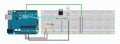
This is my first post here. I'm new to hobby electronics and have a question about a project I'm about to build. I'm going to build an Arduino project that will drive an LED strip. Since the Arduino runs on 5v, and the LED strip on 12v the directions call for a TIP122 transistor to switch the LED strip. I happened on an article that seemed to call for a MOSFET instead of the TIP122 but I'm not sure the applications are the same. I'm not only looking for an answer, I would like to understand why or why not to use either component. I did look this up in the textbook section but the material is over my head at this point.

If the MOSFET is the correct (or better) component to use, how would this change the circuit, or would it?

FLSR5D0HZ9O2AF4.MEDIUM.jpg

The project is an instructable at http://www.instructables.com/id/Under-the-bed-nightlight/?ALLSTEPS
 

MikeML

Joined Oct 2, 2009
5,444
If you are starting with an Arduino Port Pin that switches from ~0V to ~5V under program control, then either an NFET or an NPN Darlington will work. Either could switch up to >40V (depends on the rating of the NFET or NPND), up to 10s of Amps. The NFET required is a "logic Gate NFET", so be careful when specifying one.

At a load current >2A, the NFET has an advantange in that it will produce less heat than the Darlington. You might have to mount the Darlington on a heat sink, while the NFET might be usable in free air without a heat sink.

If you reduce the Arduino supply voltage to 3.3V, then the Darlington has an advantage. There are fewer NFETs that turn on properly with only 3.3V on their Gate, while it only takes a current-limited Vbe of ~1.5V to turn on the Darlington.
 

#12

Joined Nov 30, 2010
18,224
As usual (for a beginner), you have the LED in the ground side of the power transistor and no current limiting resistor for the LED. Add about 600 to 1200 ohms in the +12v line and then the LED, and then the power transistor.
 

MikeML

Joined Oct 2, 2009
5,444
He is driving a led strip, which I think has intrinsic current limiting. However, the Led strip must be connected between the +12V and the Drain/Collector of the switch. The Source/Emitter goes direct to Gnd (0V)
 

Thread Starter

Rascal

Joined Jan 2, 2015
3
If you are starting with an Arduino Port Pin that switches from ~0V to ~5V under program control, then either an NFET or an NPN Darlington will work. Either could switch up to >40V (depends on the rating of the NFET or NPND), up to 10s of Amps. The NFET required is a "logic Gate NFET", so be careful when specifying one.

At a load current >2A, the NFET has an advantange in that it will produce less heat than the Darlington. You might have to mount the Darlington on a heat sink, while the NFET might be usable in free air without a heat sink.

If you reduce the Arduino supply voltage to 3.3V, then the Darlington has an advantage. There are fewer NFETs that turn on properly with only 3.3V on their Gate, while it only takes a current-limited Vbe of ~1.5V to turn on the Darlington.
Thanks! I appreciate the thoughtful answer! The LED strip I'm using is 5 meters, 24 watts, 12v with a 2A draw. I surely won't use all 5 meters for this application so I presume the draw will be less. Sounds like the advantage goes to the Darlington based on your information. I think in the interest of safety, I'll use a heat sink in either case. As with firearms, there is no such thing as being too safe! I'm going to mount the LED strip on a piece of aluminum for the same reason. The bed frame is wood, and although the duty cycle of the strip is short, there's no sense in taking half measures. I'm a firm believer in Murphy's Law, including the corollary; "Murphy was an optimist"!
 
Top