Arduino Nano zero crossing detection

Thread Starter

mike_the_begginer

Joined Dec 7, 2019
132
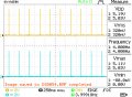
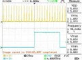
Still nothing... the temperature is not increasing, and on pin 7 there is no wave form...
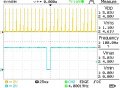
The yellow wave form is the one on pin 2.
C:
int lowError=0;
int highError=20;

//PID constants
double Kp = 2;
double Ki = 0;
double Kd = 0;

void zero() {
  counter++;
  if ((counter == 24) || (counter>duty)) {  //reach max count or duty cycle limit.
    digitalWrite(triac, LOW);
  }
  else if (counter >= 25) {
    counter = 0;
    pottemperature = analogRead(potentiometer);
    pottemperature = map(pottemperature, 0, 1023, 150, 400);
    realTemperature = thermocouple.readCelsius();
    temperature = int(0.779828 * realTemperature - 10.3427);  // make temperature an integer
    if (tempError || isnan(temperature) || temperature >= 432) { // on error kill power & set global error flag
      digitalWrite(relay, LOW); // turn off power to iron
      tempError = true;  //set error flag. can only be unset outside ISR. Once set no further action taken till unset in main loop.
    }
    else {  //reading valid
      if (temperature <= pottemperature)    { // not sure about = here, well if == then error = 0 so only rateError will have a value[S][/S]
        error = pottemperature - temperature;  // don't think you need abs() here as t cannot be > pt and get here...
        cumError += error * elapsedTime;
        rateError = (error - lastError) / elapsedTime;
        output = Kp * error + Ki * cumError + Kd * rateError;  //output error needs to be mapped to a number between 0 and 24 so...
        duty = map(output, lowError, highError, 0, 24); // lowError is const >= 0, highError is const for fully on.
        duty = constrain(duty, 0, 24); // keep duty between 0 and 24 (24 = 96%)
        if(duty) { digitalWrite(triac, HIGH);  }
        lastError = error;
      }
      else {
        duty = 0;
      }//if (temperature
    }//if (tempError
  }//if(counter == 25...
}//zero
 

Attachments

Irving

Joined Jan 30, 2016
3,884
ok...

in setup add:
C:
#define test 5
#define test1 6
pinMode(test, output);
pinMode(test1, output);
then do the following changes

C:
void zero() {
  counter++;
  if ((counter == 24) || (counter>duty)) { //reach max count or duty cycle limit.
    digitalWrite(triac, LOW);
  }
  else if (counter >= 25) {
    counter = 0;
    digitalWrite(test, HIGH); // *** added, this will generate a pulse on test pin (5) every 250mS to prove counter incrementing...
    pottemperature = analogRead(potentiometer);
    pottemperature = map(pottemperature, 0, 1023, 150, 400);
    digitalWrite(test, LOW); // *** put test pin low
    realTemperature = thermocouple.readCelsius();
    temperature = int(0.779828 * realTemperature - 10.3427); // make temperature an integer
    if (tempError || isnan(temperature) || temperature >= 432) { // on error kill power & set global error flag
      digitalWrite(relay, LOW); // turn off power to iron
      tempError = true; //set error flag. can only be unset outside ISR. Once set no further action taken till unset in main loop.
    }
    else { //reading valid
      if (temperature < pottemperature) { //*** change, remove =
        digitalWrite(test1, HIGH);  // *** added, generate a pulse on test1 (D6) when pottemp >= temp
        error = pottemperature - temperature;  // don't think you need abs() here as t cannot be > pt and get here...
        cumError += error * 250.0; //*** change - something got lost in one of my earlier edits
        rateError = (error - lastError) / 250.0; //*** change
        output = Kp * error + Ki * cumError + Kd * rateError; //output error needs to be mapped to a number between 0 and 24
        duty = map(output, lowError, highError, 0, 24); // lowError is const >= 0, highError is const for fully on.
        duty = constrain(duty, 0, 24); // keep duty between 0 and 24 (24 = 96%)
        if(duty>0) { digitalWrite(triac, HIGH); } //*** change, added '>0'
        lastError = error;
        digitalWrite(test1, LOW); // *** added
      }
      else {
        duty = 0;
      }//if (temperature
    }//if (tempError
  }//if(counter == 25...
}//zero
 

sparky 1

Joined Nov 3, 2018
757
A symetrical wave is generated from a matrix. That table has values stored some of which correspond to exact zero crossing points. These are the phase reference when the correction has been added.

The oscilloscope showing the fixed wave and the out of phase difference is in degrees.

Let's say it is a 5 degrees lag.
The sum of this lag and the reference is exactly in sync.

The data structure of the fixed matrix compared to the compensated indicated matrix is the digital conversion.
 
Last edited:

Irving

Joined Jan 30, 2016
3,884
Just seen the bug! In line 6

C:
void zero() {
  counter++;
  if ((counter == 24) || (counter>duty)) { //reach max count or duty cycle limit.
    digitalWrite(triac, LOW);
  }
 // else *** remove this
  if (counter >= 25) {
    counter = 0;
    digitalWrite(test, HIGH); // *** added, this will generate a pulse on test pin (5) every 250mS to prove counter incrementing...
    pottemperature = analogRead(potentiometer);
    pottemperature = map(pottemperature, 0, 1023, 150, 400);
    digitalWrite(test, LOW); // *** put test pin low
    realTemperature = thermocouple.readCelsius();
    temperature = int(0.779828 * realTemperature - 10.3427); // make temperature an integer
    if (tempError || isnan(temperature) || temperature >= 432) { // on error kill power & set global error flag
      digitalWrite(relay, LOW); // turn off power to iron
      tempError = true; //set error flag. can only be unset outside ISR. Once set no further action taken till unset in main loop.
    }
    else { //reading valid
      if (temperature < pottemperature) { //*** change, remove =
        digitalWrite(test1, HIGH);  // *** added, generate a pulse on test1 (D6) when pottemp >= temp
        error = pottemperature - temperature;  // don't think you need abs() here as t cannot be > pt and get here...
        cumError += error * 250.0; //*** change - something got lost in one of my earlier edits
        rateError = (error - lastError) / 250.0; //*** change
        output = Kp * error + Ki * cumError + Kd * rateError; //output error needs to be mapped to a number between 0 and 24
        duty = map(output, lowError, highError, 0, 24); // lowError is const >= 0, highError is const for fully on.
        duty = constrain(duty, 0, 24); // keep duty between 0 and 24 (24 = 96%)
        if(duty>0) { digitalWrite(triac, HIGH); } //*** change, added '>0'
        lastError = error;
        digitalWrite(test1, LOW); // *** added
      }
      else {
        duty = 0;
      }//if (temperature
    }//if (tempError
  }//if(counter == 25...
}//zero
 
Last edited:

Irving

Joined Jan 30, 2016
3,884
The comment is data structure for Zero crossing Irrelavent ?

Later than sooner you will understand eventually the code will need to be done right.
Zero crossing detection is done in hardware. There is no associated code. I've done zero-crossing in code before, it's not hard to do, no matrix required. And anyway what you wrote makes no sense in itself, it's a collection of words out of context. And still not relevant to the issue.
 

sparky 1

Joined Nov 3, 2018
757
Zero crossing detection is done in hardware. There is no associated code. I've done zero-crossing in code before, it's not hard to do, no matrix required. And anyway what you wrote makes no sense in itself, it's a collection of words out of context. And still not relevant to the issue.
Do what you want. Stop arguing I am done. But the post remains and your zero crossing is what it is.
 

Thread Starter

mike_the_begginer

Joined Dec 7, 2019
132
@Irving Please find attached the screenshots using latest code.
Screenshots 0052, 0054, 0055.jpg - pin A2 = yellow, pin A3 = blue
Screenshots 0056, 0057, 0058.jpg - pin D2 = yellow, pin D7 = blue.
The 0058.jpg is when I rotate the pot from 150 C setpoint to more than 200 C and the iron starts heating up.

LE: Now the problem is that if I disconnect iron or if I disconnect one termocouple wire then it does not show the error... and it is not turning off the relay. It only shows 0 C.

LE2: I think I found the solution for the error message problem. I modified the line:

C:
if (tempError || isnan(realTemperature) || temperature >= 432) { // on error kill power & set global error flag
I used isnan(realTemperature) instead of isnan(temperature). Now it shows the error and cuts power off when disconnecting the iron.
 

Attachments

Last edited:

Irving

Joined Jan 30, 2016
3,884
Good call on that NAN() problem.

I think we're getting closer. 0058.jpg is what I would expect to see when the iron is well below temperature.

Can you trigger on D7 rising edge and move the trigger point to the RH edge of the screen and set the time-base to 25mS/div. That should show the whole cycle.

When the iron is cold D7 should be on most of the time then as the iron gets closer to the right temperature the off time increases until it's <50% on. The exact duty cycle to maintain a given tip temperature we don't know, it will depend on thermal mass, rate of heat loss, etc.

At the moment we are running just proportional control, and Kp determines how fast the duty cycle reduces as the iron temperature approaches the set temperature. If Kp is too big the iron won't get up to temperature, too small and it will oscillate back and forth around the set point at a rate determined by the thermal delay between heater and temperature measurement.

Can you take screenshots every few seconds from cold to the lowest set point of 150C. And again after you increase the set point to 250, and again to 350.

We can log the temperature and other variables. I'll come back later with some code updates.

BTW, where are you?
 

Thread Starter

mike_the_begginer

Joined Dec 7, 2019
132
Please find attached the screenshots.
1. 0-150 C -> 92,95.jpg
2. 150-250 C -> 97,98,99.jpg
3. 250-350 C -> 104,105,106.jpg
4. 87.jpg -> the whole wave form
It is probably that I was not enough fast to capture all of the changes that appeared on the screen, because sometimes, the wave form modified/disappeared rapidly...
BTW, where are you?
Romania
 

Attachments

Irving

Joined Jan 30, 2016
3,884
Well that shows we are getting some control and the waveforms look promising - duty cycle is decreasing as temp closes on set point.

how do the temperatures look in all 3 cases above?

I think the next stage is to log data back to the PC.

I'd guessed you weren't in US because of timing... :)
 

Thread Starter

mike_the_begginer

Joined Dec 7, 2019
132
The temperature looks like:
1. If I set the temp to 150 C -> it increases from minimum temp to 154 C, then it drops to 144 C, then it stabilizes around 147-148 C.
2. If I set the temp to 250 C -> it increases from 150 C to 247 C, then it stabilizes around 244-247 C.
3. If I set the temp to 350 C -> it increases from 250 C to 350 C, then it stabilizes around 343-344 C.
 

Irving

Joined Jan 30, 2016
3,884
that's pretty good. You can't really tell but it's clear it overshoots then undershoots and finally settles on the low side.

maybe tweak Kp down to 1.5 and see how it responds...

I'll be back to my PC in a couple of hours...

Later...
 

Thread Starter

mike_the_begginer

Joined Dec 7, 2019
132
Tested with Kp = 1.5:
1. If I set the temp to 150 C -> it increases from minimum temp to 154 C, then it drops to 144 C, then it stabilizes around 148-149 C.
2. If I set the temp to 249 C -> it increases from 150 C to 250 C, then it stabilizes around 245-246 C.
3. If I set the temp to 351 C -> it stabilizes around 345-346 C.
 
Top