Facebook
 Google
 GitHub
 Linkedin
Hello, I built the circuit from this instructable: https://www.instructables.com/id/DIY-Arduino-Soldering-Station/ . I modified the schematic a bit, and it looks like this:

In the schematic, I connected a MAX6675 module on the SV1 connector and a 1602 LCD on the SV2 connector.
The code that I used is the following:
Currently I am trying to better understand the code and the working principle of this circuit.
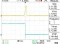
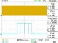
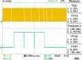
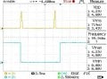
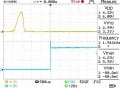
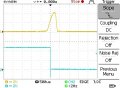
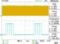
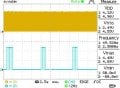
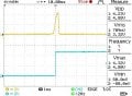
I used the oscilloscope to check the signals coming from the PC817 (yellow trace) and from D7 (blue trace) pin of Arduino Nano.


I have some problems in understanding some things and I want to ask:
1. Why the signal coming from the D7 pin is going from 5V to 0V when the signal coming from PC817 is on the rising edge ? It does not mean that it should go from 0V to 5V, on the rising edge of the PC817 signal ? It does not mean that when the signal is 0V the triac goes off and when the signal is 5V the triac goes on ?
2. Why the signal coming from D7 pin is going from 0V to 5V when there is no transition on the signal coming from PC817 ?
In the schematic, I connected a MAX6675 module on the SV1 connector and a 1602 LCD on the SV2 connector.
The code that I used is the following:
C:
#include <LiquidCrystal.h>
#include <SPI.h>
#include <Wire.h>
#include <max6675.h>

#define thermoDO 12
#define thermoCS 10
#define thermoCLK 13
#define potentiometer A0
#define zerocrossing 2
#define triac 7
#define relay A1
float temperature, realTemperature;
int pottemperature;
int counter;

byte thermometer[8] = //icon for termometer
{
  B00100,
  B01010,
  B01010,
  B01110,
  B01110,
  B11111,
  B11111,
  B01110
};

byte arrow[8] = //icon for arrow
{
  B11000,
  B01100,
  B00110,
  B00011,
  B00011,
  B00110,
  B01100,
  B11000
};

MAX6675 thermocouple(thermoCLK, thermoCS, thermoDO);

LiquidCrystal lcd(3, 4, 5, 6, 8, 9);

void setup() {
  lcd.createChar(0, thermometer);
  lcd.createChar(1, arrow);
  lcd.begin(16, 2);
  lcd.setCursor(0,0);
  lcd.print("STATIE DE LIPIT");
  delay(1200);
  lcd.clear();
  pinMode(relay, OUTPUT);
  pinMode(potentiometer, INPUT);
  pinMode(zerocrossing, INPUT_PULLUP);
  pinMode(triac, OUTPUT);
  digitalWrite(triac, LOW);
  digitalWrite(relay, HIGH);
  counter = 0;
  realTemperature = thermocouple.readCelsius();
  temperature = 0.779828 * realTemperature - 10.3427;
  updatedisplay();
  attachInterrupt(0, zero, RISING);
}

void loop() {
}

void zero() {
  counter++;
  if (counter < 40) {
    if (temperature <= pottemperature) {
      digitalWrite(triac, HIGH);
    }
    else {
      digitalWrite(triac, LOW);
    }
  }

  if (counter == 40) {
    digitalWrite(triac, LOW);
    detachInterrupt(0);
    realTemperature = thermocouple.readCelsius();
    temperature = 0.779828 * realTemperature - 10.3427;
    checkForErrors(temperature);
    updatedisplay();
    counter = 0;
    attachInterrupt(0, zero, RISING);
  }
}

void updatedisplay() {
  pottemperature = analogRead(potentiometer);
  pottemperature = map(pottemperature, 0, 1023, 150, 400);
  lcd.clear();
  lcd.setCursor(0, 0);
  lcd.write((byte)0);
  lcd.setCursor(2, 0);
  lcd.print((int)pottemperature);
  lcd.setCursor(6, 0);
  lcd.print((char)223); //degree sign
  lcd.setCursor(7, 0);
  lcd.print("C");
  lcd.setCursor(0, 1);
  lcd.write((byte)1);
  if (temperature <= 45) {
    lcd.setCursor(2, 1);
    lcd.print("Lo");
  } else {
    lcd.setCursor(2, 1);
    lcd.print((int)temperature);
  }
  lcd.setCursor(6, 1);
  lcd.print("[");
  lcd.setCursor(7, 1);
  lcd.print((int)realTemperature);
  lcd.setCursor(10, 1);
  lcd.print("]");
  lcd.setCursor(12, 1);
  lcd.print((char)223);
  lcd.setCursor(13, 1);
  lcd.print("C");
  delay(200);
}

void checkForErrors(float Temp) {
  if (isnan(Temp) || Temp >= 432) {
    while (true) {
      digitalWrite(relay, LOW); // the relay will disconnect the power to the soldering iron heating element
      // digitalWrite(triac, LOW);
      lcd.clear();
      lcd.setCursor(0, 0);
      lcd.write((byte)0);
      lcd.setCursor(1, 0);
      lcd.write((byte)0);
      lcd.setCursor(5, 0);
      lcd.print("ERROR!");
      lcd.setCursor(14, 0);
      lcd.write((byte)0);
      lcd.setCursor(15, 0);
      lcd.write((byte)0);
      delay(200);
    }
  }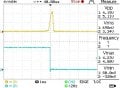
}I used the oscilloscope to check the signals coming from the PC817 (yellow trace) and from D7 (blue trace) pin of Arduino Nano.
I have some problems in understanding some things and I want to ask:
1. Why the signal coming from the D7 pin is going from 5V to 0V when the signal coming from PC817 is on the rising edge ? It does not mean that it should go from 0V to 5V, on the rising edge of the PC817 signal ? It does not mean that when the signal is 0V the triac goes off and when the signal is 5V the triac goes on ?
2. Why the signal coming from D7 pin is going from 0V to 5V when there is no transition on the signal coming from PC817 ?
Last edited: