Arduino HC 12 Power Supply

Mark Hughes

Joined Jun 14, 2016
409
Hi @Marco Carlini,
That looks like a pretty neat project. My first question is what antenna are you using? You might see decreased performance if the antenna isn't designed for the frequency range you are using. You might be able to drop down to 2400 bps and see an increased range due to increased receiver sensitivity at the lower transmission rate. You can also define the transmit power with AT+P1, AT+P2, ... , AT+P7, AT+P8. Find out what power you are currently transmitting at (AT+RP) and bump it up a level.
I wouldn't go about soldering new components on the HC12. You can likely solve your current problems with antenna selection and the choice of appropriate settings.
Mark
 

Marcomulino

Joined Nov 3, 2017
3
Today I found the problem !!
one of the hc 12 modules was defective, and in rx mode it had a low sensitivity.
Now I have replaced the module with a new one and everything works !!!!!

With a stylus antenna (buy on aliexpress) I can over 100 meters (beyond my need) with FU3 mode at 4800bps
I am very happy with the hc12 modules that I will definitely use for other projects


Thanks anyway for advice and I hope to improve my English to follow the forum more often
A greeting to all of you from italy

Marco
 

Thread Starter

Laram

Joined Oct 8, 2017
8
@Laram Any update? How are things going?
Dear Mark,

Really Sorry for not replying to you. Was travelling and was just tied up. Just returned back yesterday. Thanks to all of you for all the help you all provided. @Robin Mitchell , @Charles R. Hampton, @Jeremy Lee, @gopher T, @Mark Hughes,BR-549.

Thank you @Raymond Genovese, for the changes you suggested and all the explanation.

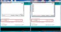
Mark, yesterday I took an Arduino Uno and a Mega I connected as you suggested with diode IN4007 and a 1000uF Capacitor between +5V and Ground. I could transfer data from the Mega to the Uno, it was only one way. The text wasn't going from the UNO to the Mega. I swapped the HC12's but still had the same problem. Then I thought the problem was due the power I took from the UNO (Original Board Italy). So I connected 4 AA cells with Booster and regulator to supply 5V, but still the text wouldn't go from UNO to Mega. I tried swaping HC12's but it was the same, one way. Baud rate is also the same 9600 and I exactly copied your program and uploaded in both the Arduinos. After some time it started transmitting junk characters. Please see attached image. Am I doing some basic mistake?

Note, I am powering Mega only from the USB. For Uno, Power is also coming from USB, but for HC-12 I am giving power from Cells. Also I have connected SMA antennas for both and not the spring antennas that came with the modules

Thanks,
Laram
 

Attachments

Last edited:

Mark Hughes

Joined Jun 14, 2016
409
@Laram,
More often than not, the junk characters are the result of a timing mismatch between the HC12 and the Arduino. You can find this pretty quickly with an oscilloscope (which is the quickest way to diagnose and solve the problem). But if you don't have one, you'll have to try different baud rates until the characters are no longer garbled.
It's possible that the HC12s are not in the pass-through mode, and have a specific baud-rate they are trying to communicate at that is different than the 9600 specified in the program. A user had a similar problem a week or two ago and solved it by writing a program that opened a serial port to the HC12 at a specific baud rate, sent "AT+DEFAULT", closed the port, incremented the baud-rate, open a port to the HC12, etc....
By stepping through all of the available UART rates, you should eventually stumble upon the correct rate and reset the unit.
If you have an oscilloscope, let me know and I'll give some more specific instructions on how to use it to diagnose your problem. Without one, you just have to stumble upon the solution.
Good luck.
Mark
 
Dear Mark,

Really Sorry for not replying to you. Was travelling and was just tied up. Just returned back yesterday. Thanks to all of you for all the help you all provided. @Robin Mitchell , @Charles R. Hampton, @Jeremy Lee, @gopher T, @Mark Hughes,BR-549.

Thank you @Raymond Genovese, for the changes you suggested and all the explanation.

Mark, yesterday I took an Arduino Uno and a Mega I connected as you suggested with diode IN4007 and a 1000uF Capacitor between +5V and Ground. I could transfer data from the Mega to the Uno, it was only one way. The text wasn't going from the UNO to the Mega. I swapped the HC12's but still had the same problem. Then I thought the problem was due the power I took from the UNO (Original Board Italy). So I connected 4 AA cells with Booster and regulator to supply 5V, but still the text wouldn't go from UNO to Mega. I tried swaping HC12's but it was the same, one way. Baud rate is also the same 9600 and I exactly copied your program and uploaded in both the Arduinos. After some time it started transmitting junk characters. Please see attached image. Am I doing some basic mistake?

Note, I am powering Mega only from the USB. For Uno, Power is also coming from USB, but for HC-12 I am giving power from Cells. Also I have connected SMA antennas for both and not the spring antennas that came with the modules

Thanks,
Laram
"After some time it started transmitting junk characters." - that is a tell and I think you are close...

Try changing the pins on the Mega first. Do not use the same pin numbers as the UNO.

See here, "Not all pins on the Mega and Mega 2560 support change interrupts, so only the following can be used for RX: 10, 11, 12, 13, 14, 15, 50, 51, 52, 53, A8 (62), A9 (63), A10 (64), A11 (65), A12 (66), A13 (67), A14 (68), A15 (69)."

Since you are using Mark's program on both, you have:
Connect HC12 "RXD" pin to Arduino Digital Pin 4
Connect HC12 "TXD" pin to Arduino Digital Pin 5
Connect HC12 "Set" pin to Arduino Digital Pin 6
and
const byte HC12RxdPin = 4; // "RXD" Pin on HC12
const byte HC12TxdPin = 5; // "TXD" Pin on HC12
const byte HC12SetPin = 6; // "SET" Pin on HC12

Try 10 and 11 for RXD and TXD, respectively on the MEGA.

If this is the problem, don't feel bad,it has caused a lot of people headaches (e.g., here)
 

Thread Starter

Laram

Joined Oct 8, 2017
8
@Laram,
More often than not, the junk characters are the result of a timing mismatch between the HC12 and the Arduino. You can find this pretty quickly with an oscilloscope (which is the quickest way to diagnose and solve the problem). But if you don't have one, you'll have to try different baud rates until the characters are no longer garbled.
It's possible that the HC12s are not in the pass-through mode, and have a specific baud-rate they are trying to communicate at that is different than the 9600 specified in the program. A user had a similar problem a week or two ago and solved it by writing a program that opened a serial port to the HC12 at a specific baud rate, sent "AT+DEFAULT", closed the port, incremented the baud-rate, open a port to the HC12, etc....
By stepping through all of the available UART rates, you should eventually stumble upon the correct rate and reset the unit.
If you have an oscilloscope, let me know and I'll give some more specific instructions on how to use it to diagnose your problem. Without one, you just have to stumble upon the solution.
Good luck.
Mark
Hello @Mark Hughes, @Raymond Genovese

Thank you for replying. :) I tried changing pins on MEGA, tried changing baud rate but no luck. There was some response (junk) from Mega to UNO but absolutely no response from UNO to MEGA. Unfortunately I do not have Oscilloscope. While searching on google I came across this link. I think it is pretty much the same what Mark has mentioned.But I am totally new to programming so couldn't modify your code. I got message, "HC12 was not declared in this scope"
// setup of the hc12 module
digitalWrite(7, LOW); // enter AT command mode
hc12.print(F("AT+DEFAULT\r\n")); // 9600, CH1, FU3, (F) to bypass flash memory
delay(100);
digitalWrite(7, HIGH); // enter transparent mode

https://forum.arduino.cc/index.php?topic=355783.30

Thanks,
Laram
 
Hello @Mark Hughes, @Raymond Genovese

Thank you for replying. :) I tried changing pins on MEGA, tried changing baud rate but no luck. There was some response (junk) from Mega to UNO but absolutely no response from UNO to MEGA. Unfortunately I do not have Oscilloscope. While searching on google I came across this link. I think it is pretty much the same what Mark has mentioned.But I am totally new to programming so couldn't modify your code. I got message, "HC12 was not declared in this scope"
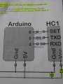
// setup of the hc12 module
digitalWrite(7, LOW); // enter AT command mode
hc12.print(F("AT+DEFAULT\r\n")); // 9600, CH1, FU3, (F) to bypass flash memory
delay(100);
digitalWrite(7, HIGH); // enter transparent mode

https://forum.arduino.cc/index.php?topic=355783.30

Thanks,
Laram
Can you please attach the two programs that you have actually loaded and run (Mark's and the one that you linked to) and identify which is UNO and which is Mega. Also, can you please post your verified connections for each (UNO and MEGA) to the HC-12 as well as the power scheme. Seems like something has been changed along the way.
 

Mark Hughes

Joined Jun 14, 2016
409
Can you please attach the two programs that you have actually loaded and run (Mark's and the one that you linked to) and identify which is UNO and which is Mega. Also, can you please post your verified connections for each (UNO and MEGA) to the HC-12 as well as the power scheme. Seems like something has been changed along the way.
Good call @Raymond Genovese -- never hurts to double check things. Also, thanks for including the information about the Mega -- having certain pins that don't function for UART can certainly be a "gotcha" type problem.

@Laram,
Follow Raymond's advice first -- double check your connections and then post pictures so someone on our end can double check your work. Remember the TX pin of the HC12 has to go to the RX pin of the Arduino and Vice Versa.
You are probably aware that data is transmitted as a series of 1's and 0's that are represented by high and low voltages. For those 1's and 0's to mean anything, the two devices involved in the communication have to agree on a protocol. The HC12 communicates with the Arduino using a protocol called UART -- Universal Asynchronous Receive & Transmit. It allows data to travel from one device to the next without a clock signal -- with the caveat that both devices have to agree on the timing in advance.

If you look at the image above, about in the middle, you'll see a line labeled "RX" followed by two interrupted dashed lines. The patterns correspond to characters. So part of the communication has to also say how many characters make up a line. A pretty popular convention is to use 8 characters for the data (ex: _,-,_,_,_,-,_,-). Note: For the time being, I'm going to ignore the parity and stop bit discussion.

One potential problem is what voltages the "high" and "low" bits are registered at. If an integrated circuit expects logic high to be at 5V, and the other circuit is producing 3.3V, they will not be able to communicate. While this is a possibility, I don't think that is the problem here.

If the two communicating devices aren't sending/receiving bits at the same speed, the receiving circuit doesn't know when to look for the transitions, and it can't figure out which character to decode. It still tries and produces garbled text.

If you're not comfortable writing an IF statement to increment the baud rate, there is another way around the problem (albeit a little slower). Go to the program and manually change all instances of 9600 to 1200, run and compile the program. Set your terminal window to 1200 and send and send the "AT+DEFAULT" command and look for an "AT+OK" reply. Then replace all instances of 1200 with 4800, and do it all over again. Walk through all of the baud rates listed in your terminal window until you get the "AT+OK" reply -- then stop.

Before you worry about getting information to float through the air, you need to confirm that you can communicate with the local HC12 attached to each Arduino. Then reset the thing and work forward from there.

Good luck,
Mark
 

Thread Starter

Laram

Joined Oct 8, 2017
8
Good call @Raymond Genovese -- never hurts to double check things. Also, thanks for including the information about the Mega -- having certain pins that don't function for UART can certainly be a "gotcha" type problem.

@Laram,
Follow Raymond's advice first -- double check your connections and then post pictures so someone on our end can double check your work. Remember the TX pin of the HC12 has to go to the RX pin of the Arduino and Vice Versa.
You are probably aware that data is transmitted as a series of 1's and 0's that are represented by high and low voltages. For those 1's and 0's to mean anything, the two devices involved in the communication have to agree on a protocol. The HC12 communicates with the Arduino using a protocol called UART -- Universal Asynchronous Receive & Transmit. It allows data to travel from one device to the next without a clock signal -- with the caveat that both devices have to agree on the timing in advance.

If you look at the image above, about in the middle, you'll see a line labeled "RX" followed by two interrupted dashed lines. The patterns correspond to characters. So part of the communication has to also say how many characters make up a line. A pretty popular convention is to use 8 characters for the data (ex: _,-,_,_,_,-,_,-). Note: For the time being, I'm going to ignore the parity and stop bit discussion.

One potential problem is what voltages the "high" and "low" bits are registered at. If an integrated circuit expects logic high to be at 5V, and the other circuit is producing 3.3V, they will not be able to communicate. While this is a possibility, I don't think that is the problem here.

If the two communicating devices aren't sending/receiving bits at the same speed, the receiving circuit doesn't know when to look for the transitions, and it can't figure out which character to decode. It still tries and produces garbled text.

If you're not comfortable writing an IF statement to increment the baud rate, there is another way around the problem (albeit a little slower). Go to the program and manually change all instances of 9600 to 1200, run and compile the program. Set your terminal window to 1200 and send and send the "AT+DEFAULT" command and look for an "AT+OK" reply. Then replace all instances of 1200 with 4800, and do it all over again. Walk through all of the baud rates listed in your terminal window until you get the "AT+OK" reply -- then stop.

Before you worry about getting information to float through the air, you need to confirm that you can communicate with the local HC12 attached to each Arduino. Then reset the thing and work forward from there.

Good luck,
Mark
Dear @Mark Hughes, @Raymond Genovese

Thank you!! Tomorrow I have a holiday. I will remove all the wires and start over again so that I don't repeat the mistake. Also I'll post the photographs and circuit. Two questions

1) To ground the SET pin of HC12 to enter command mode, can I directly connect a wire from the SET pin of HC12 to the ground of the supply?
2) Say once I change the setting to Baud Rate of HC12 to 1200, the next time I power up the HC12, will it remember it (does it save the settings in the EEPROM?) or it will go the default settings?

Thanks,
Laram
 

Thread Starter

Laram

Joined Oct 8, 2017
8
IMG_20171118_133053.jpg
Dear @Mark Hughes, @Raymond Genovese

Thank you!! Tomorrow I have a holiday. I will remove all the wires and start over again so that I don't repeat the mistake. Also I'll post the photographs and circuit. Two questions

1) To ground the SET pin of HC12 to enter command mode, can I directly connect a wire from the SET pin of HC12 to the ground of the supply?
2) Say once I change the setting to Baud Rate of HC12 to 1200, the next time I power up the HC12, will it remember it (does it save the settings in the EEPROM?) or it will go the default settings?

Thanks,
Laram
@Mark Hughes, @Raymond Genovese

I disconnected everything and did the following (Circuit is the same suggested by Mark):

Red: 5V
Green Wire: Gnd
Orange Wire: TXD
White Wire: RXD
Yellow Wire: Set
HC12 with UNO is powered via DC Voltage Booster to increase 4.8 to 9V and 5V. HC12 with MEGA is powered from Mega's 5V pin

Today the Junk Characters also stopped, absolutely no response, and MEGA was giving "ERROR" message. I noticed one thing, today on Mega both TXD and RXD LED's were blinking. Earlier only RXD LED used to blink.

UNO (Exactly same as Mark's code)

/* HC12 Send/Receive Example Program 1
By Mark J. Hughes
for AllAboutCircuits.com

Connect HC12 "RXD" pin to Arduino Digital Pin 4
Connect HC12 "TXD" pin to Arduino Digital Pin 5
Connect HC12 "Set" pin to Arduino Digital Pin 6

Do not power over USB. Per datasheet,
power HC12 with a supply of at least 100 mA with
a 22 uF - 1000 uF reservoir capacitor.
Upload code to two Arduinos connected to two computers.

Transceivers must be at least several meters apart to work.

*/

#include <SoftwareSerial.h>

const byte HC12RxdPin = 4; // Recieve Pin on HC12
const byte HC12TxdPin = 5; // Transmit Pin on HC12

SoftwareSerial HC12(HC12TxdPin,HC12RxdPin); // Create Software Serial Port

void setup() {
Serial.begin(9600); // Open serial port to computer
HC12.begin(9600); // Open serial port to HC12
}

void loop() {
if(HC12.available()){ // If Arduino's HC12 rx buffer has data
Serial.write(HC12.read()); // Send the data to the computer
}
if(Serial.available()){ // If Arduino's computer rx buffer has data
HC12.write(Serial.read()); // Send that data to serial
}
}

MEGA Code:
/* HC12 Send/Receive Example Program 1
By Mark J. Hughes
for AllAboutCircuits.com

Connect HC12 "RXD" pin to Arduino Digital Pin 10
Connect HC12 "TXD" pin to Arduino Digital Pin 11
Connect HC12 "Set" pin to Arduino Digital Pin 8

Do not power over USB. Per datasheet,
power HC12 with a supply of at least 100 mA with
a 22 uF - 1000 uF reservoir capacitor.
Upload code to two Arduinos connected to two computers.

Transceivers must be at least several meters apart to work.

*/

#include <SoftwareSerial.h>

const byte HC12RxdPin = 10; // Recieve Pin on HC12
const byte HC12TxdPin = 11; // Transmit Pin on HC12

SoftwareSerial HC12(HC12TxdPin,HC12RxdPin); // Create Software Serial Port

void setup() {
Serial.begin(9600); // Open serial port to computer
HC12.begin(9600); // Open serial port to HC12
}

void loop() {
if(HC12.available()){ // If Arduino's HC12 rx buffer has data
Serial.write(HC12.read()); // Send the data to the computer
}
if(Serial.available()){ // If Arduino's computer rx buffer has data
HC12.write(Serial.read()); // Send that data to serial
}
}

Untitled.jpg IMG_20171118_133550.jpg IMG_20171118_133303.jpg
 
Last edited:
Nice pics @Laram
For the MEGA, it looks like you have SET going to 5v and it should be going to GND (one pin over). I could be seeing things, but it sure does not look like the yellow wire is going to either of the two ground posts, but rather the 5v post. SET does not have to be on an I/O pin but it has to be at GND - no? I will keep checking and looking, but that is what I see right now.
 
Last edited:

bertus

Joined Apr 5, 2008
23,005
Hello,

I see that you have the antennas laying on the breadboard.
The breadboars will interfere with the antenna, as there are metal strips inside.
Put the antennas away from the breadboard and test again.
(not in the naberhood of metal objects).

Bertus
 

Mark Hughes

Joined Jun 14, 2016
409
@Laram,
Also, use the next bit of code in the article that implements the "Set" pin variable. I don't think you will be able to send AT commands with this method. Also, keep set low while powering on the module -- it will default to 9600 Baud and you can send "AT+DEFAULT" to reset the device. Then move the set pin to the pin defined in the sketch.
Mark
 

Thread Starter

Laram

Joined Oct 8, 2017
8
@Laram,
Also, use the next bit of code in the article that implements the "Set" pin variable. I don't think you will be able to send AT commands with this method. Also, keep set low while powering on the module -- it will default to 9600 Baud and you can send "AT+DEFAULT" to reset the device. Then move the set pin to the pin defined in the sketch.
Mark
Dear @Mark Hughes, @Raymond Genovese, @bertus

Thank you for replying. I am suspecting connection problem also. I think the Breadboard is not conducting properly. I shall update you all once I sort out this issue.

Thanks,
Laram
 

fermanbi

Joined Nov 9, 2019
4
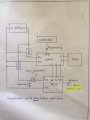
Hello, I apologize as I understand that the subject has been a matter of discussion throughout previous publications (which were useful for the development of my project). I am a civil engineer (I only have some knowledge of analog signals) and I am developing a device for sending load cell data using HC12. The signals emitted by the HC12 will be sent through a 50m long hollow steel tube 16 mm internal diameter. I read Mark Hughes's post and tried to follow the conceptual guidelines. My idea is to employ a 12V battery and two positive voltage regulators to power an ARDUINO NANO and HC12 as per the attached drawing. I understand that positive voltage regulators can supply 100mA.
It would be extremely useful for me if you looked at the sketch and suggested modifications that you considered appropriate. Similarly I would like to understand the role of the diode in the power supply of HC12) Thank you all and again apologize for coming back on a trivial subject for yousketch.jpg
 

Mark Hughes

Joined Jun 14, 2016
409
@ericgibbs Should we spin this off into its own forum topic? There's a good chance that by the time we get to a working solution, the HC12 will not be involved anymore.

@fermanbi,
First of all, you stop that "apologize for coming back on a trivial subject for you " attitude right now. Everyone has to start somewhere. And second of all, by the looks of your schematic and your problem description, the answer to your question will be far from trivial. Especially the transmission inside a metal tube.
It would help if you stated the complete problem statement that you are trying to solve. Is your requirement simply to move the signal data from one end of the pipe to the other, and you can run a wire through it? Is this a senior project where you're trying to use the pipe as a waveguide? Etc....
I'm going to start explaining some of the concerns I have with the current configuration of the project and I hope others will help chime in and take it from there.
(The Initial Electrical Concerns)

1) Anytime you have two integrated circuits that must communicate with one another, they must share a common digital logic level. Your HC12 is operating at 5V and your Nano at 10 V. The best-case scenario with a direct connection is that you'll get one-way communication (unlikely). The worst-case scenario is that the high-voltage device and the low-voltage device will be destroyed (pretty likely.) The solution to the problem is to put a single MOSFET and a couple of resistors in between the two devices -- you can buy devices such as this one from SparkFun that make it very easy to do. https://www.sparkfun.com/products/12009 (You can buy one of these, they come in pretty handy -- I purchased 4 for use on solderless breadboards and soldered a variety of different headers on them)

2) 7805, 7810, etc.... are all examples of low-efficiency voltage regulators. They produce a fixed output (provided the input voltage is above a certain threshold voltage) that is smooth and clean -- which is good, and in fact great for sensor applications as they produce virtually no noise. However, they turn a ridiculous amount of electrical energy into heat, which makes them poor choices for battery-powered devices. People use them mostly for line-powered (plugged into the wall) devices. Additionally, you'd have to look at the datasheet for your 7810 device -- A 12V input might not be sufficient for it -- it might need 12.5 V or even 13 V.

Dual output 12V/5V power supplies are ubiquitous. Here's an example: https://www.amazon.com/NOYITO-AC-DC-100-260V-Industrial/dp/B07C2MMKW3/ Unfortunately 5V/10V is going to be harder to come by. So we'll likely have to find a dual output adjustable power supply. Or, more probably, two power supplies -- a 5V and an adjustable output such as this: https://www.amazon.com/KNACRO-Adjustable-Voltage-Regulator-Supply/dp/B079DJ2GLT/ (Please don't add them to your shopping cart just yet -- I haven't researched them, I'm just using them as supporting examples)

Switching power supplies can introduce a great deal of noise into your circuit, so they aren't always great choices for signal-sensing applications, or must be chosen very carefully. But if you are trying to make your battery last as long as possible in an installation, they are often a necessary evil. Mitigation of the noise is possible -- but we can discuss that in a future post.

(The Project Stopper)

3) Alright. Here's my big concern. HC12 operates at around 450 MHz. The vacuum wavelength of that frequency is around is 66 cm. But your tube is only 16 mm across. As a radio wave begins to travel down the metal tube, it will be attenuated below the noise floor almost instantaneously. The exact cutoff frequency can be found using Bessel functions, and if you had a 16 cm or 160 cm diameter tube, I'd say it's worth doing the math. But 16mm is one-to-two orders of magnitudes too small to transmit Sub-GHz signals.

So -- let's start with the exact project description -- maybe we can find a more appropriate solution to your problem.
 

fermanbi

Joined Nov 9, 2019
4
Many Thanks Mark and all you who help me.
Which is exactly the idea: It is a device (probe) that is pushed almost statically into the ground through the use of 36mm outer diameter x 16mm inner diameter steel tubes. At the lower end is the probe consisting of pressure transducers, load cells and inclinometers. The probe commonly employs a cable for signal transmission (readings every 1 sec) but the operability of the process would benefit greatly if radio signals could be transmitted to the receiver antenna on the surface. In the hopetical case of being possible the battery should be near the probe. and the maximum prospecting distance (ie the maximum length of the pipes) is between 50 and 60m. In short, it is about sending low reading frequency sensor signals through a steel tube whose internal diameter is 16mm. Thanks again for your attention !!!
 

Mark Hughes

Joined Jun 14, 2016
409
@fermanbi,
Oh -- that's interesting. I've never tried to transmit through the Earth before. I wonder if we could use the steel tubes as the antennas? Instead of trying to transmit through the tubes, use the tubes to transmit. The SWR would likely be through the roof -- but maybe if the transmit power is low (say 1 mW) we won't burn out the transmitter. Alternatively, we could use the metal tube as a signal line -- maybe with a 1-wire protocol. Or attach an eccentric cam motor or piezoelectric actuator and make the pipe vibrate. The trouble with these ideas is that while easy to transmit, it would require an engineered receiver solution.
There are many downhole transmitters out there. Some transmit data by sending pressure waves back through the drilling mud. Others send an armored cable down the hole.
I'm certain this has been done before. Can I suggest that you post this project in a new forum topic (I don't have the ability to move it myself) and ask the wider community for help? All of the ideas that I currently have require a bit too much engineering. There's got to be an easy way to accomplish this.
 

fermanbi

Joined Nov 9, 2019
4
Great Idea Mark!
I´ll move the post of project to a new forum topic (I need to discover how to do) perhaps somebody find the topic interesting.
But the idea of use the same drilling rods as antennas may be a great solution! On the top of the last pushed rod (on ground surface) we will put the receiver!!! In this case (mantaining the model conceptually) I must connect electrically the antena output of HC12 to the pushing rod that follows the probe?? The rods are 1m long and pushed sequentially down the ground during the test
Many thanks!!!
When I discover how to create a new post I will send you the reference.
fernando


Moderators note : removed email to avoid spam
 
Last edited by a moderator:
Top