 Facebook
 Google
 GitHub
 Linkedin
Hello folks,
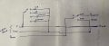
I am trying to automate the following circuitry (see attached doc.) using an Arduino, relay and a current sensor. The aim is to find the currents at each load (10kΩ, 1kΩ, 2000pF, and 20000pF). My Arduino connections are as follows:
I connected the current sensor like this:
However, I am not getting the correct measurements. I don’t know where I went wrong. Any suggestions, like using a multimeter instead of the current sensor and taking readings with the Arduino, or any other advice, would be greatly appreciated!
Thanks in advance!
I am trying to automate the following circuitry (see attached doc.) using an Arduino, relay and a current sensor. The aim is to find the currents at each load (10kΩ, 1kΩ, 2000pF, and 20000pF). My Arduino connections are as follows:
- Relay COM terminals (K1, K2, K3, and K4) are connected to point P.
- NO relay terminals are connected to each load (10kΩ, 1kΩ, 2000pF, 20000pF).
- The other end of each load is grounded.
- A 5V power supply is connected to the relay VCC, and the relay ground is connected to the common GND pin.
- Relay IN1 to IN4 are connected to Arduino digital pins D2 to D5.
- No load: Less than 1.3 mA
- 10kΩ load: Less than 1.8 mA
- 1kΩ load: Less than 3.1 mA
- 2000pF load: Less than 3.1 mA
- 20000pF load: Less than 10.0 mA
I connected the current sensor like this:
- Vin+ to point P
- Vin- to the load side (one at time)
- SCL to SCL Arduino
- SDA to SDA Arduino
- VCC to 5V
- GND to GND
However, I am not getting the correct measurements. I don’t know where I went wrong. Any suggestions, like using a multimeter instead of the current sensor and taking readings with the Arduino, or any other advice, would be greatly appreciated!
Thanks in advance!
Attachments
-
 82 KB Views: 20


