Arduino 74HC595/Seven Segment Display - Leading zeros and negative numbers issue.

ErnieM

Joined Apr 24, 2011
8,415
I would do the leading zero suppression inside the loop right after line 52.

If your tmp value is less that 999 then set digitBuffer[3] to a value of digit[] that is blank. You may have to add that.

Then if your tmp value is less that 99 then set digitBuffer[2] to a value of digit[] that is blank.

A negative sign can be added in a similar mannor.
 

Thread Starter

Remembermyname

Joined Sep 6, 2015
91
I would do the leading zero suppression inside the loop right after line 52.
That's where those are being attempted at this time. So we're in the right place it seems.

If your tmp value is less that 999 then set digitBuffer[3] to a value of digit[] that is blank. You may have to add that.

Then if your tmp value is less that 99 then set digitBuffer[2] to a value of digit[] that is blank.

A negative sign can be added in a similar mannor.
That might work as well. However, It appears that each of the commands I've tried is not working. At this time, I'm simply trying to get the digitBuffer[3] to blank outright (without the conditional) just to see if it will blank the digit. It is apparent that I'm using the incorrect syntax here with the commands I'm using past line 52. Anyone know that correct command/syntax to apply or how exactly to apply the mask?
 

Thread Starter

Remembermyname

Joined Sep 6, 2015
91
Ok. I have another way figured out. Put the changes within the digitBuffer[] calculations and add in the conditions:
Posting current code with a little cleanup. Now digitBuffer[3] is blank when it == 0 ! It throws a garbled character in to digitBuffer[3] for a second then clears up. Working on digitBuffer[2] shortly to hopefully straighten this out.

C:
/*
* http://www.pial.net/arduino-controlling-a-4-digit-seven-segment-display/
*/

//#include <OneWire.h>
//#include <DallasTemperature.h>

//#define ONE_WIRE_BUS 2

//OneWire oneWire(ONE_WIRE_BUS);
//DallasTemperature sensors(&oneWire);
//DeviceAddress insideThermometer;

const int ledPin =  13;// LED connected to digital pin 13
const int latchPin = 8;//Pin connected to ST_CP of 74HC595
const int clockPin = 9;//Pin connected to SH_CP of 74HC595
const int dataPin = 10;//Pin connected to DS of 74HC595

const int digitPins[4] = {
  3,4,5,6}; //pins to control the 4 common anode pins of the display

const byte digit[12] = //seven segment digit bits
{
  B00111111, //0
  B00000110, //1
  B01011011, //2
  B01001111, //3
  B01100110, //4
  B01101101, //5
  B01111101, //6
  B00000111, //7
  B01111111, //8
  B01101111, //9
  B00000000, //all segments off
  B01000000  //-
};

int digitBuffer[4] = {
  1};
int digitScan = 0;
int soft_scaler = 0;
float tempC, tempF;
int tmp;

void setup()  {  
  TCCR2A = 0;
  TCCR2B = (1<<CS21);
  TIMSK2 = (1<<TOIE2);
  TCNT2 = 0;
  Serial.begin(9600);

  pinMode(ledPin, OUTPUT);
  for(int i=0;i<4;i++)
  {
  pinMode(digitPins[i],OUTPUT);
  }
  pinMode(latchPin, OUTPUT);
  pinMode(clockPin, OUTPUT);
  pinMode(dataPin, OUTPUT); 

//  sensors.begin();
//  sensors.getAddress(insideThermometer, 0);
}

ISR(TIMER2_OVF_vect) {
  soft_scaler++;
  if(soft_scaler==15)
  {
  refreshDisplay();
  soft_scaler = 0;
  }
}; 

void refreshDisplay()
{
  for(byte k=0;k<4;k++)
  {
  digitalWrite(digitPins[k], LOW);
  }
  digitalWrite(latchPin, LOW); 
  shiftOut(dataPin, clockPin, MSBFIRST, B11111111);
  digitalWrite(latchPin, HIGH);
  delayMicroseconds(50);
  digitalWrite(digitPins[digitScan], HIGH);

  digitalWrite(latchPin, LOW);
  if(digitScan==1)
  {
  shiftOut(dataPin, clockPin, MSBFIRST, ~(digit[digitBuffer[digitScan]] | B10000000)); //inserting the dot
  }
  else
  {
  shiftOut(dataPin, clockPin, MSBFIRST, ~digit[digitBuffer[digitScan]]);
  }
  digitalWrite(latchPin, HIGH);
  digitScan++;
  if(digitScan>3) digitScan=0;
}

void loop()  
{
  digitalWrite(ledPin, HIGH);
  boolean sign = false;
  //sensors.requestTemperatures();
  //tempC = sensors.getTempC(insideThermometer);
  //tempF = DallasTemperature::toFahrenheit(tempC);
  //tmp = int(tempF*100);
  tempF = 12.3;
  tmp = int(tempF*10);

  //if (tmp < 0){
  //sign = true;
  //tmp = abs(tmp);
  //}

  
//  tmp = abs(tmp);


  if (int(tmp)/1000 == 0){
  digitBuffer[3] = ~(digit[digitBuffer[3]] | B00000000);
  }
//  else{
//  digitBuffer[3] = int(tmp)/1000;
//  }
//  if ((int(tmp)/1000 == 0) && (int(tmp)%1000)/100 == 0){
//  digitBuffer[2] = ~(digit[digitBuffer[2]] | B00000000);
//  }
//  else{
//  digitBuffer[3] = int(tmp)/1000;
//  digitBuffer[2] = (int(tmp)%1000)/100;
//  }
  digitBuffer[1] = (int(tmp)%100)/10;
  digitBuffer[0] = (int(tmp)%100)%10;

  Serial.print("number assigned to the variable 'tmp' = ");
  Serial.println(tmp);
  Serial.print("number assigned to the variable 'tempF' = ");
  Serial.println(tempF);
  digitalWrite(ledPin, LOW);
  delay(500);
}
 

ErnieM

Joined Apr 24, 2011
8,415
Seems you lost the second digit in your comment code.

I don't follow what you do with digitBuffer[3] when you want to blank it. Up in line 36 you define the blank character as #10 (and the negative sign as 11 next line) so why not use these directly, as in

digitBuffer[3] = 10;

Also, it is better to test the number being checked for leading zeros over checking the digit itself. What is the valid number is say 102.2? You don't want to display "1 2.2" (with a blank in there) do you?
 

Thread Starter

Remembermyname

Joined Sep 6, 2015
91
Sorry. I pasted the my scratchpad code. Below is the current code. And it works (for digitBuffer[3]). Not certain why but it appears that I may have gotten ahead of myself trying different syntax's but 'digitBuffer [3] = 10;' works. I think I was trying it with 'digitBuffer[3] = digit[10] which didn't work. Now with your suggestion in place, it was tried with 12.3 and 123.4 successfully. At least we're heading in the right direction.

'digitBuffer[3] = ~(digit[digitBuffer[3]] | B00000000);'
The digitBuffer[3] worked but without the digit[10], it was direct that also worked.

The correct code is pasted below. After this, I will work out the conditionals for digitBuffer[2].

C:
/*
* http://www.pial.net/arduino-controlling-a-4-digit-seven-segment-display/
*/

//#include <OneWire.h>
//#include <DallasTemperature.h>

//#define ONE_WIRE_BUS 2

//OneWire oneWire(ONE_WIRE_BUS);
//DallasTemperature sensors(&oneWire);
//DeviceAddress insideThermometer;

const int ledPin =  13;// LED connected to digital pin 13
const int latchPin = 8;//Pin connected to ST_CP of 74HC595
const int clockPin = 9;//Pin connected to SH_CP of 74HC595
const int dataPin = 10;//Pin connected to DS of 74HC595

const int digitPins[4] = {
  3,4,5,6}; //pins to control the 4 common anode pins of the display

const byte digit[12] = //seven segment digit bits
{
  B00111111, //0
  B00000110, //1
  B01011011, //2
  B01001111, //3
  B01100110, //4
  B01101101, //5
  B01111101, //6
  B00000111, //7
  B01111111, //8
  B01101111, //9
  B00000000, //all segments off
  B01000000  //-
};

int digitBuffer[4] = {
  1};
int digitScan = 0;
int soft_scaler = 0;
float tempC, tempF;
int tmp;

void setup()  { 
  TCCR2A = 0;
  TCCR2B = (1<<CS21);
  TIMSK2 = (1<<TOIE2);
  TCNT2 = 0;
  Serial.begin(9600);

  pinMode(ledPin, OUTPUT);
  for(int i=0;i<4;i++)
  {
  pinMode(digitPins[i],OUTPUT);
  }
  pinMode(latchPin, OUTPUT);
  pinMode(clockPin, OUTPUT);
  pinMode(dataPin, OUTPUT);

//  sensors.begin();
//  sensors.getAddress(insideThermometer, 0);
}

ISR(TIMER2_OVF_vect) {
  soft_scaler++;
  if(soft_scaler==15)
  {
  refreshDisplay();
  soft_scaler = 0;
  }
};

void refreshDisplay()
{
  for(byte k=0;k<4;k++)
  {
  digitalWrite(digitPins[k], LOW);
  }
  digitalWrite(latchPin, LOW);
  shiftOut(dataPin, clockPin, MSBFIRST, B11111111);
  digitalWrite(latchPin, HIGH);
  delayMicroseconds(50);
  digitalWrite(digitPins[digitScan], HIGH);

  digitalWrite(latchPin, LOW);
  if(digitScan==1)
  {
  shiftOut(dataPin, clockPin, MSBFIRST, ~(digit[digitBuffer[digitScan]] | B10000000)); //inserting the dot
  }
  else
  {
  shiftOut(dataPin, clockPin, MSBFIRST, ~digit[digitBuffer[digitScan]]);
  }
  digitalWrite(latchPin, HIGH);
  digitScan++;
  if(digitScan>3) digitScan=0;
}

void loop() 
{
  digitalWrite(ledPin, HIGH);
  boolean sign = false;
  //sensors.requestTemperatures();
  //tempC = sensors.getTempC(insideThermometer);
  //tempF = DallasTemperature::toFahrenheit(tempC);
  //tmp = int(tempF*100);
  tempF = 12.3;
  tmp = int(tempF*10);

  //if (tmp < 0){
  //sign = true;
  //tmp = abs(tmp);
  //}

 
//  tmp = abs(tmp);


  if (int(tmp)/1000 == 0){
  digitBuffer[3] = 10;
  }
  else{
  digitBuffer[3] = int(tmp)/1000;
  }
//  if ((int(tmp)%1000)/100) == 0) && (int(tmp)/1000 == 0))){
//  if ((int(tmp)/1000 == 0) && (int(tmp)%1000)/100 == 0){
//  digitBuffer[2] = ~(digit[digitBuffer[2]] | B00000000);
//  }
//  else{
//  digitBuffer[3] = int(tmp)/1000;
  digitBuffer[2] = (int(tmp)%1000)/100;
//  }
  digitBuffer[1] = (int(tmp)%100)/10;
  digitBuffer[0] = (int(tmp)%100)%10;

  Serial.print("number assigned to the variable 'tmp' = ");
  Serial.println(tmp);
  Serial.print("number assigned to the variable 'tempF' = ");
  Serial.println(tempF);
  digitalWrite(ledPin, LOW);
  delay(500);
}
 
Last edited:

Thread Starter

Remembermyname

Joined Sep 6, 2015
91
Seems you lost the second digit in your comment code.
Also, it is better to test the number being checked for leading zeros over checking the digit itself. What is the valid number is say 102.2? You don't want to display "1 2.2" (with a blank in there) do you?
Actually, it didn't blank the zero when I left out digitBuffer[2]. It put a zero in it's place instead of '1 2.2'. Perhaps it assumed a '0' as it received no data for digitBuffer[2] or by design of the 74HC595? Strange.
 

Thread Starter

Remembermyname

Joined Sep 6, 2015
91
Ok. digitBuffer[2] is worked out and it successfully blanks correctly with 1.2, 12.3 and 123.4 ! I will leave digitBuffer[1] alone so that .1 will be displayed as 0.1 instead of .1

On to the minus conditions.

The new code is pasted below:

C:
/*
 * http://www.pial.net/arduino-controlling-a-4-digit-seven-segment-display/
 */

//#include <OneWire.h>
//#include <DallasTemperature.h>

//#define ONE_WIRE_BUS 2

//OneWire oneWire(ONE_WIRE_BUS);
//DallasTemperature sensors(&oneWire);
//DeviceAddress insideThermometer;

const int ledPin =  13;// LED connected to digital pin 13
const int latchPin = 8;//Pin connected to ST_CP of 74HC595
const int clockPin = 9;//Pin connected to SH_CP of 74HC595
const int dataPin = 10;//Pin connected to DS of 74HC595

const int digitPins[4] = {
  3,4,5,6}; //pins to control the 4 common anode pins of the display

const byte digit[12] = //seven segment digit bits
{
  B00111111, //0
  B00000110, //1
  B01011011, //2
  B01001111, //3
  B01100110, //4
  B01101101, //5
  B01111101, //6
  B00000111, //7
  B01111111, //8
  B01101111, //9
  B00000000, //all segments off
  B01000000  //-
};

int digitBuffer[4] = {
  1};
int digitScan = 0;
int soft_scaler = 0;
float tempC, tempF;
int tmp;

void setup()  {   
  TCCR2A = 0;
  TCCR2B = (1<<CS21);
  TIMSK2 = (1<<TOIE2);
  TCNT2 = 0;
  Serial.begin(9600);

  pinMode(ledPin, OUTPUT);
  for(int i=0;i<4;i++)
  {
  pinMode(digitPins[i],OUTPUT);
  }
  pinMode(latchPin, OUTPUT);
  pinMode(clockPin, OUTPUT);
  pinMode(dataPin, OUTPUT);  

//  sensors.begin();
//  sensors.getAddress(insideThermometer, 0);
}

ISR(TIMER2_OVF_vect) {
  soft_scaler++;
  if(soft_scaler==15)
  {
  refreshDisplay();
  soft_scaler = 0;
  }
};  

void refreshDisplay()
{
  for(byte k=0;k<4;k++)
  {
  digitalWrite(digitPins[k], LOW);
  }
  digitalWrite(latchPin, LOW);  
  shiftOut(dataPin, clockPin, MSBFIRST, B11111111);
  digitalWrite(latchPin, HIGH);
  delayMicroseconds(50);
  digitalWrite(digitPins[digitScan], HIGH);

  digitalWrite(latchPin, LOW);
  if(digitScan==1)
  {
  shiftOut(dataPin, clockPin, MSBFIRST, ~(digit[digitBuffer[digitScan]] | B10000000)); //inserting the dot
  }
  else
  {
  shiftOut(dataPin, clockPin, MSBFIRST, ~digit[digitBuffer[digitScan]]);
  }
  digitalWrite(latchPin, HIGH);
  digitScan++;
  if(digitScan>3) digitScan=0;
}

void loop()   
{
  digitalWrite(ledPin, HIGH);
  boolean sign = false;
  //sensors.requestTemperatures();
  //tempC = sensors.getTempC(insideThermometer);
  //tempF = DallasTemperature::toFahrenheit(tempC);
  //tmp = int(tempF*100);
  tempF = 21.3;
  tmp = int(tempF*10);

  //if (tmp < 0){
  //sign = true;
  //tmp = abs(tmp);
  //}

   
//  tmp = abs(tmp);

 
  if (int(tmp)/1000 == 0){
  digitBuffer[3] = 10;
  }
  else{
  digitBuffer[3] = int(tmp)/1000;
  }
  if (int(tmp)/1000 == 0 && (int(tmp)%1000)/100 == 0) {
  digitBuffer[2] = 10;
  }
  else{
  digitBuffer[2] = (int(tmp)%1000)/100;
  }
  digitBuffer[1] = (int(tmp)%100)/10;
  digitBuffer[0] = (int(tmp)%100)%10;
 
  Serial.print("number assigned to the variable 'tmp' = ");
  Serial.println(tmp);
  Serial.print("number assigned to the variable 'tempF' = ");
  Serial.println(tempF);
  digitalWrite(ledPin, LOW);
  delay(500);
}
 

ErnieM

Joined Apr 24, 2011
8,415
The negative sign code goes in around line 135. At that point you have a well formed buffer with all the correct info and blanking if the number is positive.

Since your smallest negative number is -67 the negative sign is either in digitBuffer[3] or [2]. So if the sign is negative AND tmp is greater than 99 you assign digitBuffer[3] = 11; else if negative you assign digitBuffer[2] = 11;

Don't forget to check the sign at the top of loop, you commented out the sign check there.
 

Thread Starter

Remembermyname

Joined Sep 6, 2015
91
It took a minute but I have it working now. I was attempting to place the negative sign code after the digitBuffer calculations but it would give a negative sign regardless. I'm certain that it is my programming. So, I did the same with the negative condition as I had with the blanking conditions. Integrate them into the calculations. I moved the boolean out of the loop and placed it before void setup(). In the calculations, I have managed to get the '-' to follow the MSD so that -12.3 looks like -12.3 and -1.2 looks like -1.2 and not -_1.2.
-.1 looks like -0.1 .

The code is pasted below.

C:
/*Original code by:
* http://www.pial.net/arduino-controlling-a-4-digit-seven-segment-display/ ( but modified somewhat)
*/

//#include <OneWire.h>
//#include <DallasTemperature.h>

//#define ONE_WIRE_BUS 2

//OneWire oneWire(ONE_WIRE_BUS);
//DallasTemperature sensors(&oneWire);
//DeviceAddress insideThermometer;

const int ledPin =  13;// LED connected to digital pin 13
const int latchPin = 8;//Pin connected to ST_CP of 74HC595
const int clockPin = 9;//Pin connected to SH_CP of 74HC595
const int dataPin = 10;//Pin connected to DS of 74HC595

const int digitPins[4] = {
  3,4,5,6}; //pins to control the 4 common anode pins of the display

const byte digit[12] = //seven segment digit bits + blank + minus
{
  B00111111, //0
  B00000110, //1
  B01011011, //2
  B01001111, //3
  B01100110, //4
  B01101101, //5
  B01111101, //6
  B00000111, //7
  B01111111, //8
  B01101111, //9
  B00000000, //all segments off
  B01000000  //-
};

int digitBuffer[4] = {
  1};
int digitScan = 0;
int soft_scaler = 0;
float tempC, tempF;
int tmp;
boolean sign = false;

void setup()  {  
  TCCR2A = 0;
  TCCR2B = (1<<CS21);
  TIMSK2 = (1<<TOIE2);
  TCNT2 = 0;
  Serial.begin(9600);

  pinMode(ledPin, OUTPUT);
  for(int i=0;i<4;i++)
  {
  pinMode(digitPins[i],OUTPUT);
  }
  pinMode(latchPin, OUTPUT);
  pinMode(clockPin, OUTPUT);
  pinMode(dataPin, OUTPUT); 

//  sensors.begin();
//  sensors.getAddress(insideThermometer, 0);
}

ISR(TIMER2_OVF_vect) {
  soft_scaler++;
  if(soft_scaler==15)
  {
  refreshDisplay();
  soft_scaler = 0;
  }
}; 

void refreshDisplay()
{
  for(byte k=0;k<4;k++)
  {
  digitalWrite(digitPins[k], LOW);
  }
  digitalWrite(latchPin, LOW); 
  shiftOut(dataPin, clockPin, MSBFIRST, B11111111);
  digitalWrite(latchPin, HIGH);
  delayMicroseconds(50);
  digitalWrite(digitPins[digitScan], HIGH);

  digitalWrite(latchPin, LOW);
  if(digitScan==1)
  {
  shiftOut(dataPin, clockPin, MSBFIRST, ~(digit[digitBuffer[digitScan]] | B10000000)); //inserting the dot
  }
  else
  {
  shiftOut(dataPin, clockPin, MSBFIRST, ~digit[digitBuffer[digitScan]]);
  }
  digitalWrite(latchPin, HIGH);
  digitScan++;
  if(digitScan>3) digitScan=0;
}

void loop()  
{
  digitalWrite(ledPin, HIGH);

  //sensors.requestTemperatures();
  //tempC = sensors.getTempC(insideThermometer);
  //tempF = DallasTemperature::toFahrenheit(tempC);
  //tmp = int(tempF*100);
  tempF = -12.3;
  tmp = int(tempF*10);

  if (tempF < 0){
  sign = true;
  tmp = abs(tmp);
  }
  if (int(tmp)/1000 == 0){
  digitBuffer[3] = 10;
  if (sign){
  digitBuffer[3] = 11;
  }
  }
  else{
  digitBuffer[3] = int(tmp)/1000;
  }
  if (int(tmp)/1000 == 0 && (int(tmp)%1000)/100 == 0) {
  digitBuffer[2] = 10;
  if (sign){
  digitBuffer[2] = 11;
  digitBuffer[3] = 10;
  }
  }
  else{
  digitBuffer[2] = (int(tmp)%1000)/100;
  }
  
  digitBuffer[1] = (int(tmp)%100)/10;
  digitBuffer[0] = (int(tmp)%100)%10;

  Serial.print("number assigned to the variable 'tmp' = ");
  Serial.println(tmp);
  Serial.print("number assigned to the variable 'tempF' = ");
  Serial.println(tempF);
  digitalWrite(ledPin, LOW);
  delay(500);
}
I can now call this portion of the project successful. Thank you so much for your insight. Now to add the sensor.
 

ErnieM

Joined Apr 24, 2011
8,415
You are most welcome. Thanks for coming back with your results.

I'd suggest you start a new thread for the sensor portion.

Good luck!
 

MMcLaren

Joined Feb 14, 2010
861
Hi Remembermyname (Lawrence). Nice job, especially considering the lack of comments and description in the original source project.

Would you mind if I asked a couple questions for the Arduino gurus, please?

(1) Based on the program, what is the Timer 1 interrupt interval (display refresh rate)?

(2) Does Arduino force a 'fixed' frequency or period for the PWM functions?

I was thinking it might be cool to add PWM brightness control by modulating the 74HC595 output enable pin, which implies scanning the display at the PWM period interval. I've done this on PIC projects but I'm still quite new to Arduino.

Thanks in advance.

Cheerful regards, Mike

MacMux 4-Digit 16F88 Demo.PNG
 
Last edited:

djsfantasi

Joined Apr 11, 2010
9,237
With regard to question 2, the Arduino uses a fixed frequency on its PWM pins. You control the duty cycle. The actual frequency depends on the pins used or the type of Arduino. Most pins use 490Hz, but some run at 980Hz.
 

Thread Starter

Remembermyname

Joined Sep 6, 2015
91
Hi Remembermyname (Lawrence). Nice job, especially considering the lack of comments and description in the original source project.
Thanks MMcLaren. But I found myself stuck without help from others. The original code from the original author didn't provide much description or comments either. Getting the code figured out (sort of) was one thing, but it was trying to understand what to search for was bigger issue. I'm slowly learning as I go along.

I was thinking it might be cool to add PWM brightness control by modulating the 74HC595 output enable pin, which implies scanning the display at the PWM period interval. I've done this on PIC projects but I'm still quite new to Arduino.
I still consider myself new to arduino (or the whole MCU world) myself. Sending PWM to the 74HC595 from the Arduino shouldn't be impossible. I hadn't considered it until you mentioned it and that might be a nice feature. At that point, I was simply trying to get rid of those annoying zeros and figure out how to deal with the negative numbers situation. Thank you @djsfantasi . The abs() function did work well.
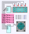
Sometimes the end user might not want a bright display GLARING out at them. Because I'm using the blue display I have in the picture in the first post, it CAN light up a dark room. :D
 

MMcLaren

Joined Feb 14, 2010
861
I'm still learning Arduino and AVR, too. I hope you don't mind me trying to understand the operation of the program a little more. It's a shame the original author didn't provide a better description and meaningful comments in the source code.

I think I've figured out the Timer2 setup. Hopefully the Arduino/AVR gurus will correct me if I'm wrong. It seems Timer2 is setup to use the system clock (16-MHz) with prescaler = 8 for a 2-MHz (128-us) overflow interrupt interval. Basically, the Timer2 interrupt is firing every 2048 clock cycles. The Timer2 overflow interrupt routine updates one digit every 16 interrupts at 2048-us intervals. It takes four of these 2048-us intervals (8192-us) to refresh the entire display so we have a 25% duty cycle and a ~122-Hz refresh rate.
Code:
  void setup() {
 /*                                                           *
  *  setup Timer 2 for 128-us (2-MHz) overflow interrupts     *
  *                                                           */
    TCCR2A = 0;               // TMR2 'normal' mode
    TCCR2B = (1<<CS21);       // prescale 8 (2-MHz/128-us)
    TIMSK2 = (1<<TOIE2);      // enable 'overflow' interrupt
    TCNT2 = 0;                //
I think I've figured out how to setup Timer2 to generate a PWM signal and interrupt (below) but I'll save that experiment for another thread.

Take care. Have fun. Cheerful regards, Mike

Code:
  void setup() {
 /*                                                                          *
  *  setup Timer 2 for "fast PWM" mode on OC2A(D11) with a 128-us period     *
  *                                                                          */
    pinMode(strobe, OUTPUT);                // OC2A(D11) PWM pin 'output'
    TCCR2A = 1<<COM2A1|1<<WGM21|1<<WGM20;   // OC2A(D11) non-inv PWM mode
    TCCR2B = 1<<CS21;                       // prescale 8 (2-MHz/128-us)
    OCR2A = 128;                            // 50% duty cycle
    TIMSK2 = 1<<TOIE2;                      // enable 'overflow' interrupts
 
Last edited:
I didn't look at the code, but a "trick" when you want leading zeros to say a 3 digit number, you add 1000. Assuming strings. So, if you had 3, it turns into 1003,so now if you output the right 3 digits. So, you have a number like 256.3, multiply by 10, do the round stuff if needed, and add 10000. So, you would get 12563 or if it was 53.1, 100531. All you would have to do is check the 2,3 and 4th digit for zero and set a flag for the first non-zero digit. So, if the flag is zero AND the digit is zero, replace with a "space". Doing it for just the 2, 3 and 4th digit, you do display 0.0 for 0. Your decimal point is in a fixed location.
 
Top