Arduino 5v PWM to 12v PWM

Thread Starter

s200bym

Joined Aug 9, 2017
82
Hi All,

To start with, I am no electronics specialist, I am just a hobbyist who is after some help, please.

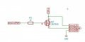
I have a 12v servo that needs a 12v PWM signal to do the magic. I have been browsing the net and have come up with the below schematic. Could someone with a better knowledge of electronics confirm that this is the right way of doing it?
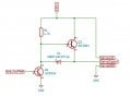
12v PWM.JPG

Regards,
Mike.

Moderators note : uploaded picture to forum
 
Last edited by a moderator:

Reloadron

Joined Jan 15, 2015
7,976
Would the circuit be something like this? And would it be worth adding an opto isolator to stop any 12v leaking into the arduino pin?

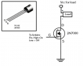
Not quite, using a 2N7000 N Channel MOSFET you want to do low side switching. In the below image you would also want to add about a 10K resistor from the MOSFET Gate to Ground. The resistor will ensure the MOSFET turns off when it is supposed to.

2N7000 Example.png

Ron
 

MaxHeadRoom

Joined Jul 18, 2013
30,873
So the servo is connected to 12dc, power common, and the drain of the Mosfet to the servo input.
I assume this is a RC servo?.
Max.
 

Thread Starter

s200bym

Joined Aug 9, 2017
82
The servo needs both 12v dc power and a separate 12v PWM signal. would connecting the servo signal to drain not just connect it to ground?

It's not an RC servo but it acts just the same.

Mike.
 

Reloadron

Joined Jan 15, 2015
7,976
Thought about this a little and realized you are using a servo. I doubt a servo control line draws much current. Additionally using an N type switch, be it a simple transistor or a MOSFET the signal out will be inverted. So for example if you use a common PRT (Pulse Repetition Time) of 20 mSEC (50 Hz) and have a pulse On Time of 1.5 mSEC +/- 0.5 mSEC from a uc (Micro-Controller). The pulse out will be inverted using a N type switching device in my drawing. That would involve changing the code and I see it as a nightmare. What you want can be done but will take an additional transistor. That is my tired thinking on this.

Max, would that be correct?

Ron
 
Last edited:

Reloadron

Joined Jan 15, 2015
7,976
You want similar. Have to take my wife to a treatment. Soon as I get home I'll give you a drawing of what you want that should work fine.

Ron
 

Reloadron

Joined Jan 15, 2015
7,976
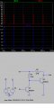
Here is what you want.

5V to 12V Pulse.png
V2 labeled in is the 5 volt pulses, V1 is your 12 VDC supply voltage and Vout is your motor control 12 VDC pulses. The 2N3904 is fine but any PNP switching transistor will work even a 2N2222.

Ron
 

Reloadron

Joined Jan 15, 2015
7,976
Don't you need a current limiting resistor on the base of Q1? If not, what limits current from the Arduino PWM output?
Yeah, you may want to try a 2.2K base resistor on Q1 base going to the Arduino. That should get the base current of Q1 down below about 2 mA. Thanks for pointing that out.

Ron
 

ian field

Joined Oct 27, 2012
6,536
Hi All,

To start with, I am no electronics specialist, I am just a hobbyist who is after some help, please.

I have a 12v servo that needs a 12v PWM signal to do the magic. I have been browsing the net and have come up with the below schematic. Could someone with a better knowledge of electronics confirm that this is the right way of doing it?

View attachment 165582

Regards,
Mike.

Moderators note : uploaded picture to forum
A cas-code stage is a popular level shifter design. The MPU output pin replaces the bottom common emitter transistor. the top transistor is common base so the pin must sink all the current coming from Rl at the top. its high output impedance means you'll need to hang an emitter follower on the end to drive anything much. If you don't mind the output being out of phase - just use a logic level MOSFET and tie Rl to 12V.
 

Thread Starter

s200bym

Joined Aug 9, 2017
82
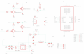
I got the 5v PWM signal to bump up to 12V using the schematic in my last post. I just need to sort the code out to get the right frequency of the PWM signal.

Mike.
 
Top