Facebook
 Google
 GitHub
 Linkedin
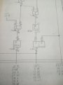
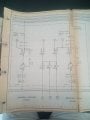
Dear all, I have attached part of an old machine electrical schematics. In the schematics there are symbols of rectangular and square shape inside these shape the following presents
1. Just the figure 1
2. Greater than or equal to 1 seemingly
3. S and R
4. Inverted triangle and 2A
Any one who knows the meaning
1. Just the figure 1
2. Greater than or equal to 1 seemingly
3. S and R
4. Inverted triangle and 2A
Any one who knows the meaning
Attachments
-
 1.2 MB Views: 73