Facebook
 Google
 GitHub
 Linkedin
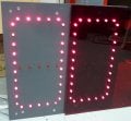
I've taken on a project that is making me stretch quite a bit, and thought I'd seek some wisdom about it. I'm pretty early on in my hobby electronics phase, so bear with me. It is very similar to this build, but simplified a little. Here is a quick sketch-up render I did.

Essentially, 2 groups of 2 digit 7-segment displays, each one able to count up or down via green and red buttons. It will be used in our assembly shop to keep track of how many fixtures are done during the day. The left side will be the "active" number, and the right side being the "target" number. Functionally, though, they should act identically (mostly for simplicity).
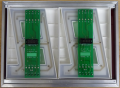
I'm planning on using two separate boards for each side, and ideally using one power supply and one on/off switch (that would also act as a reset).
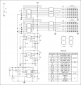
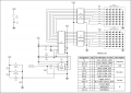
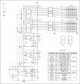
The closest circuit to what I think I need was also referenced in the noted thread, created by elec_mech and attached below.

And now we get to my question. The 7-segment displays I was planning on using are from Jameco, Part Number 105591 and the counter IC was a CD40110B, also from Jameco. My inexperience is making it hard to understand exactly how much voltage and current those 7-segments are going to need. I assume I'll need Darlington transistor between the counter IC and the LEDs, but I'm lost as to figuring out which one.
I'm also wondering about a power supply. Since I'd like to use one to power both sides, will that need some additional circuitry to work? Or do I just need something with double the amps that a single side would require?
Thanks in advance for any help. I've been scouring away these forums and others for the past few days, and have learned much just from reading.
P.S. Assuming that I'm able to make one of these boxes happen, my employer will then be asking for 9 more. So hopefully I'm not driving myself off a cliff here.
Essentially, 2 groups of 2 digit 7-segment displays, each one able to count up or down via green and red buttons. It will be used in our assembly shop to keep track of how many fixtures are done during the day. The left side will be the "active" number, and the right side being the "target" number. Functionally, though, they should act identically (mostly for simplicity).
I'm planning on using two separate boards for each side, and ideally using one power supply and one on/off switch (that would also act as a reset).
The closest circuit to what I think I need was also referenced in the noted thread, created by elec_mech and attached below.
And now we get to my question. The 7-segment displays I was planning on using are from Jameco, Part Number 105591 and the counter IC was a CD40110B, also from Jameco. My inexperience is making it hard to understand exactly how much voltage and current those 7-segments are going to need. I assume I'll need Darlington transistor between the counter IC and the LEDs, but I'm lost as to figuring out which one.
I'm also wondering about a power supply. Since I'd like to use one to power both sides, will that need some additional circuitry to work? Or do I just need something with double the amps that a single side would require?
Thanks in advance for any help. I've been scouring away these forums and others for the past few days, and have learned much just from reading.
P.S. Assuming that I'm able to make one of these boxes happen, my employer will then be asking for 9 more. So hopefully I'm not driving myself off a cliff here.
Attachments
-
111.1 KB Views: 115
") You've told us very clearly what you're trying to accomplish, provided pictures to better illustrate what you want to do, and provided links to parts/datasheets you plan to use. Kudos! If every first post looked like this, we could help members much faster.
You've told us very clearly what you're trying to accomplish, provided pictures to better illustrate what you want to do, and provided links to parts/datasheets you plan to use. Kudos! If every first post looked like this, we could help members much faster.