Analogue scope not triggering

Thread Starter

andrew331

Joined Apr 28, 2015
14
Analogue scope not triggering
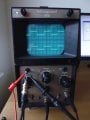
I have a 1970s Telequipment D61a which will not trigger. Altering the trigger level control or setting it on auto has no effect. I can sometimes get a stable trace by adjusting the time base. It is then only stable on one particular setting. I have a service manual and have attempted two adjustments, ‘trigger sensitivity’ and ‘sweep stability’ but no effect. It is the same on both channels.
As this seems a relatively simple scope, with no chips and the transistors are all in sockets, I thought I might be able to repair it. Apart from the triggering it works fine!
Could you point me in the right direction?
Thanks
Andrew
 

MrChips

Joined Oct 2, 2009
30,802
Do you have an oscilloscope? :p

You will need to get the circuit schematics.

What I really mean is, give me a chance to look over the circuit.
 

MrChips

Joined Oct 2, 2009
30,802
Do you have a BNC cable/adapter in order to connect the CAL output to the EXT input?

Set the trigger select to EXT.
 

Thread Starter

andrew331

Joined Apr 28, 2015
14
With the CAL output connected to channel 2 or channel 1 I can get an almost steady square wave with the time base set at 5ms/div.
Changing the trigger selector ext/ch 1/ ch2 does nothing.
Now CAL connected to EXT input and trigger select to ext, gives just a horizontal trace.
 

Thread Starter

andrew331

Joined Apr 28, 2015
14
I now have CAL connected to ch 1 and to EXT.
ch2 is turned off.
I can still get the square wave at 5ms/div, increasing time/div gives me what looks like a square wave moving left to right,
decreasing time/div it looks like maybe a square wave that is not triggering.
The trigger level control still does nothing.
 

MrChips

Joined Oct 2, 2009
30,802
We understand that the triggering is not working and this is because of a fault in the circuitry and not because of incorrect operation.

So what we will attempt to do is to use your scope to locate the fault.
With the power unplugged, you will remove the cover of the unit and familiarize yourself with the locations of all the boards. Consult the service manual.

How comfortable are you with following schematic diagrams and relating it to actual components on the circuit boards?

For the time being, keep the unit unplugged from AC mains and don't go poking fingers into the unit. There are potentially lethal high voltages in there.

Do you have any experience trouble shooting electronic equipment in a similar situation?

You also understand that AAC members are located across the globe and there are time zone differences. Expect some delays in responses as some of us do work, eat and sleep.
 

Thread Starter

andrew331

Joined Apr 28, 2015
14
Thanks, that sounds great.

Electronics was a hobby of mine when I was young and now I am retired I want to learn more which is the reason I bought this old scope.
I have basic knowledge of electronics, mostly analogue, and will recognise the components and will be able to follow the circuit diagrams .
No experience of troubleshooting anything as complex as this.
I have the instruction manual which as well as the operating instructions has circuit descriptions and diagrams, which I will try to attach to this post as a pdf.
 

Attachments

MrChips

Joined Oct 2, 2009
30,802
That's ok. I have the service manual too. I will post the relevant schematics and PCB drawings as we progress.
I can't work on this at the moment.

But just so you know where we're going.

You are going to connect the CAL output to CH 1 input and TRIG input simultaneously, with switch set to EXT.
You will connect a scope probe (preferable a x10 probe) into CH2 input. You will use the CH2 probe to trace what becomes of the trigger signal.

First test, with above setup, power on, connect the CH2 probe to the CAL signal and verify that CH1 and CH2 inputs and traces are correct.
 

MrChips

Joined Oct 2, 2009
30,802
Thanks.

Now POWER OFF and unplug the AC cord.
Open the unit and locate the board shown on page 38. We are going to trace the circuit shown on page 29.
We are going to look at the signals at TR23 at the top left of page 38. Get familiar with the board layout.

Which side of the board do you have access to? The component side or solder side?

I will post pics later.
 

MrChips

Joined Oct 2, 2009
30,802
Here is the circuit schematic on Page 29. We want to look at the signal at the base and collector of TR23.
You will take two scope views at each test point using CH2 input:

1) with the input channel switch set to DC in order to measure the DC bias. You need to show on your scope screen where is the 0V (GND setting) reference line,

2) with the input channel switch set to AC in order to measure the AC peak-to-peak voltage.

In the case of the signal at the base (R32) only one measurement is required since the signal is expected to be centered about 0V.


Here is what the solder side of the board looks like. When you get the chance, post a photo of your view (component side).


Thread Starter

andrew331

Joined Apr 28, 2015
14
At the first test point (R32) I find a waveform like that shown in the manual but only 20 mV p - p.

The second test point (R33) I could not find. My version of the circuit diagram, see below, is slightly different and R33 and C27 are not there.
It looks like this scope is a later modified version as these two components do not appear in the component list either.

What I have done is to probe the cathode of D27 as this looks to be connected directly to the collector of TR25.
What I find is a DC 10v, no sign of any AC.

upload_2015-4-29_21-35-32.png
 

MrChips

Joined Oct 2, 2009
30,802
If you have a DMM (Digital MultiMeter) can you measure the voltages at the collector, base and emitter with respect to GND at both TR23 and TR25?
If you are not sure how to do this safely then wait for further instructions. It is important that you don't make a bad situation worse by burning out good components.

One thing to be aware of. There is a +/- switch to the right of the trig/ext x input jack.
Do the scope test and the DMM measurements with the switch set to + and repeat with the switch set to -.
 
Last edited:

Thread Starter

andrew331

Joined Apr 28, 2015
14
DMM readings:

switch at - switch at +
TR23
collector 11.59V 10.25V
base 0.12mV 0.96mV
emitter -0.615V -0.614V

TR25
collector 10.35V 11.52V
base 37.68mV 37.64mV
emitter -0.604V -0.604V

Scope results:
TR23
base
approx. 20mV square wave with no dc offset
this is the same with the switch in either position

collector
9.6V with switch set to +
10.8V with switch set to -

What I missed yesterday is that there is a approx. 20mV square wave on top of this dc .
 

Thread Starter

andrew331

Joined Apr 28, 2015
14
MrChips

I will be away from home now for about three weeks.
If you can help me progress with it when I get back that will be great.
Many thanks for you help so far.

Andrew
 

MrChips

Joined Oct 2, 2009
30,802
Sorry about not being able to get back to you.
The information that you have supplied suggests that the trigger signal is getting through to that point. We have to look further along the chain to look for the fault.

When you get back we will pick up where we left off.
 

Thread Starter

andrew331

Joined Apr 28, 2015
14
Sorry about not being able to get back to you.
The information that you have supplied suggests that the trigger signal is getting through to that point. We have to look further along the chain to look for the fault.

When you get back we will pick up where we left off.
Hi Mr Chips,

Back home now.
Any more help you can give with this will be appreciated.

Andrew
 
Top