
Hello!
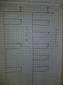
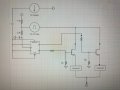
I have a 20 V analog signal that runs anywhere form 20-50 Hz and has a duty cycle that changes depending on how long a solenoid is needed to stay open. Basically is a DC pulse. I am attempting to essentially remove (split between two solenoids) every other pulse from the signal line, or in other words double the period, and split the duty cycle in half. Im looking for some suggestions on how to get this accomplished with hardware you could find in a school lab. Im currently using a voltage divider to run the clock off this signal on a J-K flip flop to adjust the signal (to no avail) then some Mosfets to deliver the 20 v signal power. If anyone has some ideas on how they would approach the issue let me know!
I have a 20 V analog signal that runs anywhere form 20-50 Hz and has a duty cycle that changes depending on how long a solenoid is needed to stay open. Basically is a DC pulse. I am attempting to essentially remove (split between two solenoids) every other pulse from the signal line, or in other words double the period, and split the duty cycle in half. Im looking for some suggestions on how to get this accomplished with hardware you could find in a school lab. Im currently using a voltage divider to run the clock off this signal on a J-K flip flop to adjust the signal (to no avail) then some Mosfets to deliver the 20 v signal power. If anyone has some ideas on how they would approach the issue let me know!
Attachments
-
 1.5 MB Views: 18
 -
 6.3 MB Views: 22


