 Facebook
 Google
 GitHub
 Linkedin
Hello,
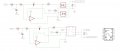
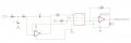
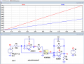
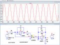
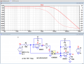
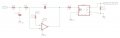
I need an assistance to design an analog input from variable pott with optocoupler (dc stable side to dc not stable side), the output needs to be accurate so I thought of using 2 optos pc8117. but i found a linear one HCNR200 and would like to change the design to work with this one. i am not sure if the bellow sketch with the linear is correct, can you advice please? also are the other components seems ok?
I need an assistance to design an analog input from variable pott with optocoupler (dc stable side to dc not stable side), the output needs to be accurate so I thought of using 2 optos pc8117. but i found a linear one HCNR200 and would like to change the design to work with this one. i am not sure if the bellow sketch with the linear is correct, can you advice please? also are the other components seems ok?
Attachments
-
 97.5 KB Views: 49

")


