Analog isolation amplifier circuit

Thread Starter

L Cal

Joined Oct 13, 2015
12
Hi there,

I am new to this forum and I am looking for some suggestions.

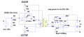
In my application I have some isolated hall effect current and voltage sensors, each giving an output current (IM) up to +/-50mA (e.g. LEM LAX 100-NP). This current then goes to a resistor (R1) and gets converted into a +/-10V signal, which is then measured by another circuit (not displayed below). I have represented the secondary of the LEM sensor in the picture below.

Screen Shot 2017-09-16 at 10.33.08 PM.png

As you can see, the ground GND1 is connected to GND2 and this is undesired and causes malfunctioning in the circuit. Is there a way to provide galvanic isolation (drawn by green dashed lines in the picture) between the output of the sensor and the resistor R1? so that GND1 and GND2 are no longer connected? Any product out there that can do the job, with a high precision and high bandwidth?

I noticed that perhaps the HCNR200 integrated circuit can help to achieve the required isolation. Do you know of any circuit configuration using HCNR200 which can help achieve the galvanic isolation required in the picture above?

Thank you very much for your time,

Lello
 

ericgibbs

Joined Jan 29, 2010
21,408
hi Lello,
Is possible to move R1 to use the GND1 as its return,? and then use the HCNR in bipolar configuration to isolate the +/-10V across R1.
E
 

Thread Starter

L Cal

Joined Oct 13, 2015
12
Hi Eric,
thank you for your reply. I cannot move R1 unfortunately, the only solution is to "cut" the cable connecting R1 to the sensor output, and insert galvanic isolation. If you know of any circuit using HCNR200 that could work it would be great.
Thank you so much
Lello
 

dendad

Joined Feb 20, 2016
4,635
I'm not sure why you have 2 grounds, and as to what goes wrong with the measurement. A bit more info would help. What is the "malfunction"?
Can you explain a bit better what is the problem?
Having GND1 and GND2 connected as shown, there are 2 single points that have no other connection, so there is no electrical path for anything to take place. That would be ok, but if you are having problems, there must be other connections too. Trying to work out what is going on with such limited info is hard.
You need to supply a more detailed connection diagram. Don't leave out your monitoring equipment.

(I've designed quite a lot of industrial control equipment and have been caught by funny grounds before).

If your monitoring equipment is running on 24V for example, try a 24V to +/- 15V supply and just have one ground, the 24V common point. Connect the +/- 15V 0V point to the 24V 0V.
 

ian field

Joined Oct 27, 2012
6,536
hi.
A possible alternative would be to cut the cable, add a resistor say R2 of the same value as the existing R1.
Let the R2 drive into a HCNR bi-polar config and the output from the HCNR drive the existing R1 as it's load resistor.
You have not stated the value of R1.?
E

EDIT:

You could consider a Isolation Amp.
http://www.analog.com/en/products/amplifiers/isolation-amplifiers.html
It can also be done with discretes; one opto manufacturer published an appnote describing an opto coupler based isolator, a second opyo in series with the signal PD drives the op amp feedback loop to ensure a linear transfer curve. This obviously requires a power supply on the isolated side - there are off the shelf isolation chips with integrated isolating SMPSU in the package. There are opto coupler types and various kinds of inductive coupled methods.
 

Thread Starter

L Cal

Joined Oct 13, 2015
12
hi.
A possible alternative would be to cut the cable, add a resistor say R2 of the same value as the existing R1.
Let the R2 drive into a HCNR bi-polar config and the output from the HCNR drive the existing R1 as it's load resistor.
You have not stated the value of R1.?
E

EDIT:

You could consider a Isolation Amp.
http://www.analog.com/en/products/amplifiers/isolation-amplifiers.html
Hi Eric,

Thanks for your reply. R1 = 200 Ohm so that it gives +/-10V when IM = +/-50mA. Yes, that is what I was also thinking; i.e. to insert R2 = R1 on the side connecting the terminal M to GND1 ad a galvanic isolator downstream, isolating R1 from R2 (in order to eliminate the connection between GND1 and GND2).

Given the voltage requirement across R1 and R2 (of +/-10V) is there any specific circuit you would recommend?

Thanks

Lello
 

ericgibbs

Joined Jan 29, 2010
21,408
hi,
There are Power OPA's available, LT1497 and OPA569 or you could use a medium power OPA and add output transistors.

Use the HCNR withCA3240's

E
EDIT: CA3240
 
Last edited:

ericgibbs

Joined Jan 29, 2010
21,408
hi Lello,
This draft LTSpice sim is one option.
Uses 2 off HCNR for bi-polar isolation, CA3240 OPA's and a power amp push pull Class A output into a 200R Load.
Checked over a temperature range of 0C thru 100C, the BD's should have an heat sink.

E
 

Attachments

Thread Starter

L Cal

Joined Oct 13, 2015
12
hi Lello,
This draft LTSpice sim is one option.
Uses 2 off HCNR for bi-polar isolation, CA3240 OPA's and a power amp push pull Class A output into a 200R Load.
Checked over a temperature range of 0C thru 100C, the BD's should have an heat sink.

E
Hi Eric,

Thank you very much, it is a fine solution the one you are proposing.

However, in order to limit the component count I was thinking to use a power op-amp at the output stage, as you have suggested, in this way avoiding to use the push-pull class A amplifier. I have run some simulations where I put the power amplifier OPA453 at the output; this power amplifier can be supplied at high voltage, and give a maximum current of 50mA at the output, which is what I need. At the input stage I have used LT1354 amplifier, not for any particular reason, except that they can be supplied supplied from a +/-15V source. This is the resulting model:Screen Shot 2017-09-19 at 9.49.45 PM.png
While the output voltage is a "copy" of the input voltage on an isolated ground circuit as desired, I still have some doubts about the results:

1) the shape of the output voltage (green waveform) seems to have some problem when the input voltage (red waveform) is close to zero, some sort of nonlinearity which I am not sure what is the cause.

Screen Shot 2017-09-19 at 9.58.18 PM.png

2) in the simulation above, the frequency of the signal is 1kHz. If I perform simulations with a 10kHz input signal, the output voltage does not result to be of the desired shape, as is something is not working properly.
Screen Shot 2017-09-19 at 10.04.41 PM.png

Which leads to my next question:

3) what is the way to ensure the desired bandwidth in this system? The needs for my application is to have a bandwidth of 100kHz or so.

Thank you so much for your input. I attach my simulation files for reference.

Lello
 

Attachments

ericgibbs

Joined Jan 29, 2010
21,408
hi,
Could you run a AC Analysis sim of your circuit at the input and output of OPA453.?

I suspect the response is not flat, also I would be interested in seeing response curve, say from 1Hz thru 1 MHz

E
BTW: I do not have the LTS models for the HCNR201 and OPA453.
 

ericgibbs

Joined Jan 29, 2010
21,408
hi Lello,
Using a HCNR200 and a CA3140 with a 10K load resistor, I see this response on LTSpice. Voltage BW just over 100kHz.
Note: reduced the 10pF's to 4.7pF
The positive/negative cross over problem starts around 200Hz, this maybe an artefact of the LTS models of the HCNR/@LT1354.????
Ref attached plots.
E
Simplified the power rails for the sim only.!

EDIT:
Use BA282 diodes in place of the 1N914, its 1.2pF versus 4pf inter capacitance of the 1N914, improves the BW.!
Can you say what the project is actually measuring that requires, +/-10V at +/-50mA at 100kHz.?
 

Attachments

Last edited:

Thread Starter

L Cal

Joined Oct 13, 2015
12
It can also be done with discretes; one opto manufacturer published an appnote describing an opto coupler based isolator, a second opyo in series with the signal PD drives the op amp feedback loop to ensure a linear transfer curve. This obviously requires a power supply on the isolated side - there are off the shelf isolation chips with integrated isolating SMPSU in the package. There are opto coupler types and various kinds of inductive coupled methods.
hi,
Could you run a AC Analysis sim of your circuit at the input and output of OPA453.?

I suspect the response is not flat, also I would be interested in seeing response curve, say from 1Hz thru 1 MHz

E
BTW: I do not have the LTS models for the HCNR201 and OPA453.
Hi Eric,

Thanks for your answer. The application deals with measurement of control signals coming from a power converter, probably the value I gave are a bit over sized, nevertheless I will try to target them.

The response curve of the OPA452 is below:
OPA453.JPG
OPA453-1.JPG

I think that the problem in the simulation of the full system with HCNR201 was due to the value of resistance linking the two different grounds (R_isol). Once I set this value to 1kOhm (rather than 999MEG) it seem to work. The current across this resistor (R_isol) is anyway negligible. In this way I can keep simulating the two different grounds, and this is the result I get:
solution_sch.JPG

Note that I have used OPA452 which is similar to OPA453. Also I have reduced the capacitor values at the input stage to 4.7pF and adopted diodes with very small junction capacitance (Cj=0.16pF).

solution_voltages.JPG

The frequency response is as follow:
solution_frequency.JPG

Also, I got the model of the HCNR201 from here if you are interested, and the TI OPA452/3 from the TI website, by downloading the .lib file and creating the part from it automatically.

Regards

Lello
 

ericgibbs

Joined Jan 29, 2010
21,408
hi Lello,
It looks as though you have working design, try replacing the SD4148 diode with the BA282 model and re-run the AC response sim, you should see an increase in the BW of the HCNR block.

I also noticed in LTSpice by trying different, lower values of the 10meg COM to Gnd resistor, the 'glitch' at the pos/neg changeover was affected.

Are you now going to build a bench model of the project in order to prove the LTS sims.?
Will be interested to see the final results.

Eric
I will get those HCNR201 and OPA452 models.

EDIT:
Noticed your diode change to 0.16pF, ignore my BA232 suggestion.!
 

Thread Starter

L Cal

Joined Oct 13, 2015
12
Hi Eric,

thanks for your help and your reply. Probably it was the link between the two grounds causing the glitch at the pos/neg changeover. Yes, I am going to try to build a prototype in the near future. I will keep you posted on the results.
thanks again

Lello
EDIT: the distortion near zero volt is actually a characteristic of this circuit -rather than a simulation glitch-, as reported in the datasheet of HCNR200/1 (page 17, top of right column: see below). Probably because the LED does not turn on if the voltage across it is too close to zero volt...

Note.JPG
 

Thread Starter

L Cal

Joined Oct 13, 2015
12
EDIT: the distortion near zero volt is actually a characteristic of this circuit -rather than a simulation glitch-, as reported in the datasheet of HCNR200/1 (page 17, top of right column: see below). Probably because the LED does not turn on if the voltage across it is too close to zero volt...

View attachment 135470
EDIT 1: in order to reduce this crossover, D1 and D2 are used. As recommended in pag 18, right column at the bottom
Note-2.JPG
 

xox

Joined Sep 8, 2017
936
It can also be done with discretes; one opto manufacturer published an appnote describing an opto coupler based isolator, a second opyo in series with the signal PD drives the op amp feedback loop to ensure a linear transfer curve. This obviously requires a power supply on the isolated side - there are off the shelf isolation chips with integrated isolating SMPSU in the package. There are opto coupler types and various kinds of inductive coupled methods.
Interesting, and it looks like there are plenty of options for a wide range of voltages too. Good to know!
 
Top