Analog demultiplexer - signal deformation

Thread Starter

fabiangiana

Joined Aug 10, 2016
6
Hello everyone,

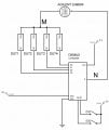
I need to measure the spectral impedance of different DUTs (Devices Under Test) in sequence, i.e. one after another. So I'm trying to use an analog demultiplexer to switch between the DUTs automatically. The problem is that the measured impedances of the DUTs change when the Demux is connected, i.e. there is a deformation of the resulting signals across the DUTs.

According to the datasheet of the IC (CD4052B) , the ON resistance of the channels is very low in comparison with the impedances of the DUTs, and the cutoff frequencies are far above my measurement frequencies.

Some characteristics of the equipment:

Demultiplexer: CD4052B (DC voltage source: +- 5 V)
LCR-meter: Agilent E4980a
Frequency range: 20 Hz - 100 kHz
Signal amplitude: <= 100 mVrms
Impedance range of the DUTs: 1 kOhm - 1 MOhm

I don't understand the source of the error, but even if it's unavoidable: is there a way to correct/compensate the values? I tried the Open-Short-Load compensation described in page 4-6 of the "Agilent Impedance Measurement Handbook", but the compensation was not satisfactory.

If necessary, I could give quantitative examples.
 

crutschow

Joined Mar 14, 2008
34,468
Are those DUTs truly floating as you show, no other connections?
What are those DUTs?
If they are truly floating, then try tieing point N or M to common (ground).
Circuits generally don't like floating nodes.
 

Thread Starter

fabiangiana

Joined Aug 10, 2016
6
Are those DUTs truly floating as you show, no other connections?
What are those DUTs?
If they are truly floating, then try tieing point N or M to common (ground).
Circuits generally don't like floating nodes.
Thank you very much for your answer. Each DUT is a microelectrode array in contact with an electrolytic solution. But I also tried with a simple resistor in series with a capacitor and the problem persists.

One side of the DUTs is connected to a "common ground", wich is always connected to one of the terminals of the LCR-meter. The other side of each DUT is connected to a corresponding output of the demultiplexer. Even if the inactive DUTs were floating, the active one wouldn't, so that doesn't seem to be the problem.
 

AnalogKid

Joined Aug 1, 2013
11,055
You don't say how big the error ("deformation") is. Note that a CD4051 running on +/-5 V can have over 500 ohms of on-resistance, a significant percentage of your DUT 1 K minimum impedance. Also, the on-resistance varies as a function of the signal voltage amplitude, a sure source of harmonic distortion. What about 4 small reed relays? Hard to beat for simplicity and on resistance.

ak
 

Thread Starter

fabiangiana

Joined Aug 10, 2016
6
You don't say how big the error ("deformation") is. Note that a CD4051 running on +/-5 V can have over 500 ohms of on-resistance, a significant percentage of your DUT 1 K minimum impedance. Also, the on-resistance varies as a function of the signal voltage amplitude, a sure source of harmonic distortion. What about 4 small reed relays? Hard to beat for simplicity and on resistance.

ak
Thank you for answering. Here you can find an example of this "deformation". I modelled the DUTs as RC-series circuits and plotted the resistance and capacitance spectra for two different channels. The DUTs are different and with impedance values greater than 1 kOhm. As you can see, the effect is more noticeable at low frequencies. It's true that the ON resistance varies with the signal voltage amplitude, but it should always be way smaller than the impedance of the DUTs.

I was thinking about the relays, but I actually need in the order of 100 channels, so it would be a little too expensive. But if the analog demultiplexer doesn't work the way I need, I will try your suggestion. Thank you!
 

Attachments

crutschow

Joined Mar 14, 2008
34,468
.................
One side of the DUTs is connected to a "common ground", wich is always connected to one of the terminals of the LCR-meter. The other side of each DUT is connected to a corresponding output of the demultiplexer. Even if the inactive DUTs were floating, the active one wouldn't, so that doesn't seem to be the problem.
I still don't see a ground path between the DUT circuit and the MUX common.
You need the mux common connected to your "common ground".
Is that connection made?
 

AnalogKid

Joined Aug 1, 2013
11,055
It's true that the ON resistance varies with the signal voltage amplitude, but it should always be way smaller than the impedance of the DUTs.
Yes, it *should* be, but no, it isn't. 75-to-125 is not way less than 1000.

Also, if I read your images correctly the change in capacitance with and without the analog mux goes from 4 nF to 5 uF, a change of 1,250-to-1. Wha???

ak
 

Thread Starter

fabiangiana

Joined Aug 10, 2016
6
I still don't see a ground path between the DUT circuit and the MUX common.
You need the mux common connected to your "common ground".
Is that connection made?
Sorry, I misunderstood your first answer! You wanted me to connect the common output of the DUTs to the GND of the demultiplexer. Well, I tried that and it did the trick! Now I'm getting the same impedance values with and without the demux.

A good example of an amateur mistake.

Thank you very much!
 

Thread Starter

fabiangiana

Joined Aug 10, 2016
6
Yes, it *should* be, but no, it isn't. 75-to-125 is not way less than 1000.

Also, if I read your images correctly the change in capacitance with and without the analog mux goes from 4 nF to 5 uF, a change of 1,250-to-1. Wha???

ak
Yes, it *should* be, but no, it isn't. 75-to-125 is not way less than 1000.

Also, if I read your images correctly the change in capacitance with and without the analog mux goes from 4 nF to 5 uF, a change of 1,250-to-1. Wha???

ak
I meant that the impedance values of the example are much higher than 1 kOhm. Nevertheless, you are right: the ON resistance is not always negligible.

And yes, the change in capacitance was THAT big. However, I changed the connections as proposed by crutschow and now I'm getting a better result.

Thank you very much for your time and help.
 

crutschow

Joined Mar 14, 2008
34,468
Sorry, I misunderstood your first answer! You wanted me to connect the common output of the DUTs to the GND of the demultiplexer. Well, I tried that and it did the trick! Now I'm getting the same impedance values with and without the demux.

A good example of an amateur mistake.
...................
A very small nit. ;) You are actually using the 4052 as a multiplexer (many into one), not a demultiplexer (one into many).

But glad it's now working for you.
Just remember that one of the primary rules of circuits is that all parts of a circuit almost always need to be referenced in some manner to a common ground.
The only exception is if you are deliberately isolating one circuit from another, as with a transformer or optical isolator.
Otherwise you can get strange results, as you observed.

But don't feel bad. It's a common mistake for newbies in circuit design to miss that requirement and then wonder why their circuit doesn't work properly.
 
Top