An unusual error in my hacked DMM FS8233

sarahMCML

Joined May 11, 2019
703
I am starting your circuit mister @Danko
One thing I learn in my past, is that Zenner diodes are extremely sensitive to currents. Pretty much like LED's.
I have added a minimum protection of 100R on that zener. Actually 100R will be like nothing is there, at least 500R in my experience, but I will close an eye on this and try it riskier with 100R. Which is foolish of me. Also is a bit high value of 16V. I have a good range of zenners. We should include 12V or a bit less to be in specs with the VReg I have. If you dont know already, this AMS1117 that I use, is accepting voltages up to 15V. I usually put it in circuits with 12V, never to its maximum of 15.V.
Make these 2 modifications in your simulator and see if the results are still ok.
Thank you.
In this case putting any resistor in series with the Zener diode is the last thing you should do. Its purpose here is to limit the positive going voltage swing on the turned off transistor collector. Adding a resistor allows the voltage to become higher, and could get to the point where the transistors exceed their collector-emitter breakdown voltage. Your 100 Ohms hasn't made too much difference in this case: 500 may have!
 

Danko

Joined Nov 22, 2017
2,222
Also I suggest to include in your next simulation test, this VReg circuit as well. Because it is part of the circuit after all.
This circuit not works in simulator. Its designed and tested by brain and hands. Oscillograms in post #133 are real oscillograms of real voltages in real circuit.
Some notes:
1. Seems you are not able exactly follow instructions.
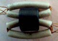
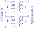
2. Can you read drawings at all? See how my transformer looks like:
1668981592146.png
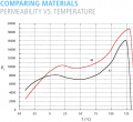
3. Are you sure permeability of your ferrite ring is similar to permeability of LFB090050-000 ring which I bought on Digikey?
Ferrite_40_42.PNG
4. Do not believe readings of PS ammeter. Use DMM for all current measurements.
5. Show us oscillograms of voltages on transistors collectors.
6. Put 3.2 V instead of batteries to FS8233 and measure maximal current, consumed on every range of measurement (probes of FS8233 should be shorted).
 
Last edited:

Thread Starter

q12x

Joined Sep 25, 2015
2,227
Well, we tried our best. Subject is closed. I move on and use it as is.
Thanks everyone for collaboration and help !
Your very best friend, mister q12 !
 

DickCappels

Joined Aug 21, 2008
10,662
I can't help thinking that if you were to get serious about following up on suggestions you would have exactly what you wanted and you would have learned a lot. At least you have something to show for your effort.
 

BobTPH

Joined Jun 5, 2013
11,616
I can’t help but think his problem all along was good incorrect wiring. His transformers were not perfect but they should have worked if wired correctly.
 

Danko

Joined Nov 22, 2017
2,222
Now LCR meter MS5308 is arrived, so I did some measurements.

Transformer:
1669340573441.png

Drawing
View
Minimal breakdown voltage between primary and secondary sides = 4000 V
Capacitance between primary and secondary sides = 1.5 pF

Core:
LFB090050-000
Ferrite ring OD = 9 mm, ID = 5 mm, H = 7 mm
Material “42”, µ initial = 7500 (identified with help of Coil64 program)

Windings I-IV, each:
10 turns wire dia 0.19 mm (32.5 AWG)
L = 528 µH
R @DC = 0.27 Ω
R @10 kHz = 1.032 Ω
 
Last edited:
Top