Amplifying wave generator signals

Thread Starter

kevinnas

Joined Jul 31, 2017
77
Hello.
I have an Arbitrary wave generator which produces different signals. At the moment I have it set to produce up to 1V p-p pulse signals (50ns wide and 5khz frequency) and I need to amplify this to pulse transducers at 100V p-p.
My problem is coming up with a power amp design that can faithfully amplify the input.
Does anyone have any suggestions ? I may also need the gain to be adjustable and for use with 1Mhz-35mhz signals

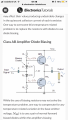
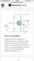
I was thinking maybe a class A amplifier using transistors or mosfets (not sure which type Would be best so advice here would be appreciated) or to go for a class AB circuit like the one attached. My only concern with these circuits is that I may not be able to get the 100Vdc p-p output? Because everywhere I have looked these circuits have been used to amplify millivolts up to maybe 10Vdc and at low frequencies.

I have also seen some circuits with different stages which combine both the circuits attached. A class A stage then Class AB stage. Or some with a comparator/op amp at the first stage then class AB. And some with a with a transformer but I am not sure which type would be suitable for my application. Please any help will be appreciated greatly.
 

Attachments

Last edited by a moderator:

Bordodynov

Joined May 20, 2015
3,177
Yes I know, I am not sure if you are trying to give me a hint because I have not got it unfortunately.
I'll think about it. But the task is not simple. In fact, you need an aperiodic amplifier with a wide frequency range. Realization of this is very difficult, if not to use special and large lamps for radio transmitters. If the harmonic signal is amplified, the output power is 50 V * 1 A / 2 = 25 W.
 

Thread Starter

kevinnas

Joined Jul 31, 2017
77
Can you still want the output impedance to be 50 ohms?
Another thing is the 1V p-p input is the absolute maximum that the AWG can produce, so I could technically reduce the input for example 0.1Vdc p-p etc just have a higher gain amplifier ( 1000 instead of 100 ) to produce the required 100V p-0 output if that helps?
At the moment I have no idea what type of circuit to have a look at or what class amplifier or if its to be transistor based/op amp/mosfet based etc. If you could point me in the right direction too that would be useful so I am not just stuck as I am right now.
 

Bordodynov

Joined May 20, 2015
3,177
Do you think that these conditions are easily met? I disappoint you, this is a difficult task and I doubt that you are able to do it. If a pulse signal could be received (50 ns, 100 V), then a harmonic signal, I do not know how to do it. Perhaps if you try to do using a low-voltage amplifier (Vcc = 30V, push-pull) and a step-up transformer. But a 30 W broadband transformer is also very difficult to do. Try to find something on the Internet, but I doubt that you will find what you need. I wash hands.
 

Thread Starter

kevinnas

Joined Jul 31, 2017
77
Do you think that these conditions are easily met? I disappoint you, this is a difficult task and I doubt that you are able to do it. If a pulse signal could be received (50 ns, 100 V), then a harmonic signal, I do not know how to do it. Perhaps if you try to do using a low-voltage amplifier (Vcc = 30V, push-pull) and a step-up transformer. But a 30 W broadband transformer is also very difficult to do. Try to find something on the Internet, but I doubt that you will find what you need. I wash hands.
No I do not think it’s easy at all. I am just wondering what could make it easier, some of the specifications could possibly be relaxed if it is absolutely necessary & makes the task doable. Like the output voltage could possibly be lower or anything else
 

AnalogKid

Joined Aug 1, 2013
10,987
To faithfully reproduce a 50 ns pulse, you need an amplifier bandwidth of at least 200 MHz. If it were a symmetrical square wave, 100 MHz would get you the first four harmonics, so the output pulse would be sorta-kinda square-ish, but it will have sloped sides (maybe so sloped that the top of the pulse is more of a point than a flat top) and ringing. Plus other unknown distortions caused by phase shift as the harmonic frequencies approach the amplifier's corner frequency. 200 MHz gets you a few more harmonics for squareness, and moves the phase distortions out where then have a smaller percentage effect on the signal.

But, your duty cycle is 4000:1, so you are basically amplifying isolated pulses, not a continuous waveform. This makes the the required harmonic spectrum for some level of fidelity more complex, and wider.

If you have a big bucket of money, Amplifier Research specializes in this kind of thing. https://www.arww-modularrf.com/amplifier_systems.cfm

If the output always is a pulse, as in not sine, not triangle, not arbitrary, etc., then I'd look into saturated switch circuits as opposed to linear amplifiers. Timing will be tricky, but fast power MOSFETS with *big* gate drivers is a reasonable starting point.

Separate from all of that, you want a 200 W (peak power) output. That's a lot. No matter how you do it, conceptually you're looking at a medium-low power FM radio station.

ak
 

Thread Starter

kevinnas

Joined Jul 31, 2017
77
To faithfully reproduce a 50 ns pulse, you need an amplifier bandwidth of at least 200 MHz. If it were a symmetrical square wave, 100 MHz would get you the first four harmonics, so the output pulse would be sorta-kinda square-ish, but it will have sloped sides (maybe so sloped that the top of the pulse is more of a point than a flat top) and ringing. Plus other unknown distortions caused by phase shift as the harmonic frequencies approach the amplifier's corner frequency. 200 MHz gets you a few more harmonics for squareness, and moves the phase distortions out where then have a smaller percentage effect on the signal.

But, your duty cycle is 4000:1, so you are basically amplifying isolated pulses, not a continuous waveform. This makes the the required harmonic spectrum for some level of fidelity more complex, and wider.

If you have a big bucket of money, Amplifier Research specializes in this kind of thing. https://www.arww-modularrf.com/amplifier_systems.cfm

If the output always is a pulse, as in not sine, not triangle, not arbitrary, etc., then I'd look into saturated switch circuits as opposed to linear amplifiers. Timing will be tricky, but fast power MOSFETS with *big* gate drivers is a reasonable starting point.

Separate from all of that, you want a 200 W (peak power) output. That's a lot. No matter how you do it, conceptually you're looking at a medium-low power FM radio station.

ak
The power output maximum could be rated at 30W, at the moment using a 50ohm bnc dummy load and I am using an arbitrary wave generator so input may not always be a pulse it could be a sine wave or square or anything. If absolutely necessary I could pulse the transducers at much less than 5khz. I will be doing work within 1-35MHz center frequency. Usually around 10-20Mhz so 200MHz and 200W is overkill. Maybe I wasn’t clear or said something before that contradicts this.
 

AnalogKid

Joined Aug 1, 2013
10,987
The 200 W is peak power, the power necessary for a 50 ohm load at 100 V. Granted it is for a fraction of a millisecond, but that is what the output stage has to deliver electrically. Thermally, the output stage does not need to be anywhere near this beefy. I get a total energy per pulse of 10 microwatt-seconds.

ak
 

ebp

Joined Feb 8, 2018
2,332
Saying "peak to peak" isn't sufficient information. A signal that is unipolar (i.e. either positive-going with respect to "ground" or negative-going) usually requires much simpler circuitry than a signal that swings both positive and negative with respect to ground.

The exact nature of the transducer also makes a big difference. A purely resistive transducer, which is something of a rarity, is comparatively easy to drive. If the sensor has a reactive component (inductance or capacitance) then it may be necessary to both source current into it and sink current from it in order to force the desired waveshape. This is true even if the required waveshape is unipolar. If the transducer is resonant, then it can probably be quite adequately excited by "pinging" it with pulses, either single or repetitive.
 

Thread Starter

kevinnas

Joined Jul 31, 2017
77
To faithfully reproduce a 50 ns pulse, you need an amplifier bandwidth of at least 200 MHz. If it were a symmetrical square wave, 100 MHz would get you the first four harmonics, so the output pulse would be sorta-kinda square-ish, but it will have sloped sides (maybe so sloped that the top of the pulse is more of a point than a flat top) and ringing. Plus other unknown distortions caused by phase shift as the harmonic frequencies approach the amplifier's corner frequency. 200 MHz gets you a few more harmonics for squareness, and moves the phase distortions out where then have a smaller percentage effect on the signal.

But, your duty cycle is 4000:1, so you are basically amplifying isolated pulses, not a continuous waveform. This makes the the required harmonic spectrum for some level of fidelity more complex, and wider.

If you have a big bucket of money, Amplifier Research specializes in this kind of thing. https://www.arww-modularrf.com/amplifier_systems.cfm

If the output always is a pulse, as in not sine, not triangle, not arbitrary, etc., then I'd look into saturated switch circuits as opposed to linear amplifiers. Timing will be tricky, but fast power MOSFETS with *big* gate drivers is a reasonable starting point.

Separate from all of that, you want a 200 W (peak power) output. That's a lot. No matter how you do it, conceptually you're looking at a medium-low power FM radio station.

ak
Maybe if the input doesnt have to be reproduced absolutely perfectly like maybe the fundamental not and harmonics reproduced.
At the moment the task seems possibly too difficulty so I am just trying to see what can make it easier. I do not want to buy anything off the shelf because I may want to modify the design in the future and add different functions. If 100V p-p is too much as an output I could settle for 50Vp-p which would make the power 50W.
I just need something to work with I guess?
 

Thread Starter

kevinnas

Joined Jul 31, 2017
77
Saying "peak to peak" isn't sufficient information. A signal that is unipolar (i.e. either positive-going with respect to "ground" or negative-going) usually requires much simpler circuitry than a signal that swings both positive and negative with respect to ground.

The exact nature of the transducer also makes a big difference. A purely resistive transducer, which is something of a rarity, is comparatively easy to drive. If the sensor has a reactive component (inductance or capacitance) then it may be necessary to both source current into it and sink current from it in order to force the desired waveshape. This is true even if the required waveshape is unipolar. If the transducer is resonant, then it can probably be quite adequately excited by "pinging" it with pulses, either single or repetitive.
For now p-p means 0-1V so if that makes things easier then ill be okay with that. however, in the future I may need both positive and negative swing so if this doesn’t add too much complexity would be better but not necessary. As far as I the transducers are resistive, maybe they do have a reactive component I am not too sure about that part
 

AnalogKid

Joined Aug 1, 2013
10,987
At these frequencies, the connection usually is coax cable or some other constant-impedance structure.

If so for you, do you need a source with a 50 ohm output impedance to suppress reflections?

If so, then the output voltage before the source terminator needs to be 200 V peak to deliver 100 V peak into the load.

This gets into a whole different thing about what the output impedance is during voltage changes. For pulse signals you can use saturated switches pulling up and down, but the output impedance goes to infinity between the time the pull-up turns off and the pull-down turns on. Not for very long, but some applications are more sensitive than others. For arbitrary waveforms you have no choice but a true linear amplifier. Depending on what the load is, you could go with a current source output stage - half the voltage but twice the current.

Is the output waveform unipolar or bipolar? If unipolar, how close to GND does it have to get?

ak
 

BR-549

Joined Sep 22, 2013
4,928
See if you can find a signal generator amp. I bought a FeelTech FY6600-30M a while back.

20V p-p at 50 ohms out. DC -30MHz. Already. They had a wideband amp for it.

OOPS....forget that....the amp only goes to 3 MHz.

I did find an amp with your specs using google.......solid state, about the size of a desk and over 5000 bucks.

A linear amp with that frequency range is quite a task.
 

Thread Starter

kevinnas

Joined Jul 31, 2017
77
At these frequencies, the connection usually is coax cable or some other constant-impedance structure.

If so for you, do you need a source with a 50 ohm output impedance to suppress reflections?

If so, then the output voltage before the source terminator needs to be 200 V peak to deliver 100 V peak into the load.

This gets into a whole different thing about what the output impedance is during voltage changes. For pulse signals you can use saturated switches pulling up and down, but the output impedance goes to infinity between the time the pull-up turns off and the pull-down turns on. Not for very long, but some applications are more sensitive than others. For arbitrary waveforms you have no choice but a true linear amplifier. Depending on what the load is, you could go with a current source output stage - half the voltage but twice the current.

Is the output waveform unipolar or bipolar? If unipolar, how close to GND does it have to get?

ak
The load is piezoelectric and can be damaged by any voltages above 200V and yes I will be using coax cables & bnc connectors. I do not know about the source having 50 ohm impedence for reflections part.
The input from the AWG is either just a normal square pulse from 0-1V or it could either be a negative swinging hann like pulse (something like the attached) going from -0.5V to 0.5V
The same is true for thenoutput
 

Attachments

Top