Facebook
 Google
 GitHub
 Linkedin
If you are investigating behavior then you probably do need to be able to drive various waveforms, however ...
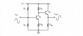
I used to be involved with instrumentation for ultrasonic transducers used in non-destructive testing (pipeline welds). The transducers were piezo types with resonant frequencies of typically 5, 10 or 15 MHz. The transmit signal was generated by exciting the transducer with a single very narrow pulse of about 400-450 V which would yield a current of 8-9 A, at least at the input end of the 50 ohm cable (which was long enough that the driver was all done before the pulse arrived at the transducer). The circuitry to do this was quite simple.
A piezo transducer is going to be reactive and because it is resonant the impedance will vary dramatically with frequency.