Facebook
 Google
 GitHub
 Linkedin
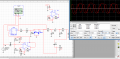
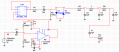
It's about an octave down guitar effect, I uptaded the schematic as an attachment. Basically, I'm amplifying the guitar signal and leaving it biased, the flip flop will then produce a square wave, which I will center and smooth it, turning it into a 'sine wave' (looks like one). Finally, I use a high pass filter to level the amplitude at differente frequencies as best as I could, since 100Hz would get way more voltage than 300Hz. After this high pass filter I get from 296uV to 660V (300 Hz and 100Hz), and since it's not really a sine wave, I'm struggling to amplify it. I need to amplify it to around 100mV-200mV.
Attachments
-
 17 KB Views: 24