I guess you did not make my mic preamp circuit where the input of the opamp is biased to half the supply voltage with 3 resistors, not just two resistors. It biases the mic with 1 resistor from a filtered voltage. Please post your schematic.
You do not want to match the input impedance of the amplifier to the impedance of the microphone. You want the input impedance of the amplifier to be much higher than the impedance of the mic so the level from the mic is not loaded down.
oh i got ur point now! so i think either something wrong in my circuit or maybe the connection! pls check my schematic! i'll try to use ur preamp as well.
It is too bad that you did not make my mic preamp circuit that works. Yours is completely wrong. You also saved your schematic as a fuzzy JPG file type instead of as a very clear PNG file type.
i just didn't use yours because i wanted to learn from my mistakes instead of just following a ready circuit!
i tested the mic by detecting the herat sound and i connected it directly to the oscilloscope, the maximum output voltage was 800mV! n i wanted it to be in the range from 0-5V that's y i want low gain! but anyway it will be bigger than 2.2K!
i'll test and work on your circuit now! thanks a lot
No.
An electret mic needs the Fet transistor inside to be powered or it does not work.
The output level of an electret mic is about 5mV to 25mV, not 800mV.
You do not want to match the input impedance of the amplifier to the impedance of the microphone. You want the input impedance of the amplifier to be much higher than the impedance of the mic so the level from the mic is not loaded down.
We generally consider the signal to be a voltage. The (series) output impedance of any device forms a potential divider with the input inpedance of the next. The signal voltage divides between the two in the normal ratio. So the larger the input impedance of the following device the greater share of the available voltage it will receive.
This is what Audioguru meant by not loading the device. Follow his good advice to make your circuit work.
We match impedances if we want to generate power in the following device ie transfer power to it. This is known as the maximum power transfer theorem. This theorem does not apply in your application.
Then I was young we did not have any internet. But I learned a lot by browsing through data books and study circuit examples. And so can you. If you take a circuit given to you and work with it until you understand it you have learned something. And you can also learn a lot by simulating your circuit.
Then you ask questions in this forum it is also important that you post the circuit you are using in the first posting. That will ensure you that we do not go around blindfolded trying to help you. And you get your answer much faster.
I have to agree with t06afre, There is a lot to be said from learning from OTHERS mistakes, so you don't have to make them.
When you get a ready made circuit, simulate it the way you would have done it and see what you get differently. But don't destroy your equipment for pride.
Don't be afraid to ask why it works, that will get you the same education, with less burnt up equipment.
i tested your circuit today but i only changed R1 resistior value to 2.2K as stated in my mic datasheet! (i don't know if this gonna affect the values of other components !?)
the circuit has amplified the signal well but it didn't bias it, although it amplified the both side of the signal !
will i get a value of half of the supply voltage if i connected the output directly to the multimeter ? or is it observed on the oscilloscope that the signal is biased up ?
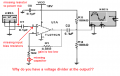
one more thing, what's the role of 1K resistor in your circuit ? i tried to remove it but it didn't work without it !!
Then I was young we did not have any internet. But I learned a lot by browsing through data books and study circuit examples. And so can you. If you take a circuit given to you and work with it until you understand it you have learned something. And you can also learn a lot by simulating your circuit.
Then you ask questions in this forum it is also important that you post the circuit you are using in the first posting. That will ensure you that we do not go around blindfolded trying to help you. And you get your answer much faster.
The gain is set by VR1 and R4. To simplify analysis think about C2 as a device that block DC 100% and have Zero resistance for AC. Let us also say the that no current will flow into the OPAMP input. Then for DC this circuit will have gain equal to 1, and for AC the gain will be (1+VR1/R4)
The value of R1 is affected by the supply voltage. 2.2k might work well if the supply is only 3V.
Most electret mics use a current of 0.5mA. With a 12V supply and allowing for 4V across the mic then the 1k and 2.2k resistors will have 6V across them and will have a current of 1.975mA which is too high. The 2.2k resistor value is too low and will reduce the output level from the mic. If R1 is 10k then the current is 6V/11k= 0.55mA which is good.
The circuit has amplified the signal well but it didn't bias it, although it amplified the both side of the signal!
I don't know what you mean "but it didn't bias it". My circuit uses R2 and R3resistors to bias the input of the opamp to half the supply voltage.
Will i get a value of half of the supply voltage if i connected the output directly to the multimeter? Or is it observed on the oscilloscope that the signal is biased up?
It makes a filter with the 47uF capacitor so that fluctuations in the supply voltage do not feed into the input of the opamp. The bias voltage for the opamp and the bias current for the microphone pass through the 1k resistor so the circuit will not work without it.
With a single supply voltage, the minimum output voltage of a TL071 opamp is about +1V and its maximum output voltage is 1V less than its supply voltage. You want the output to swing more positive and less positive so its input and output should be biased at half the supply voltage.
The opamp in my preamp circuit has a DC gain of 1 so its output DC voltage is the same as its input DC voltage.
i have tested the circuit on a software simulation program just now, i found out that when i remove the 0.33uF capacitor it gives me a signal in positive range ( i mean the reference voltage is around half of supply voltage) but i connect the capacitor the reference voltage becomes Zero! can i just remove this capacitor? i want positive range to use it with AD converter!
 Facebook
 Google
 GitHub
 Linkedin
 18.8 KB Views: 16