Amplifier Layout Question

Thread Starter

mertkan65

Joined Mar 20, 2017
17
Dear All,

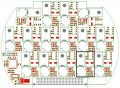
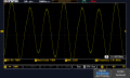
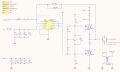
We have 15 channel class AB type amplifier on single PCB. All these channels generated with same schematic with top sheet and room layout. 14 Channel works fine with calculated gain but 1 channel has a low gain according to others. We have try many things but we could not identify problem. Except Input and output of the channels, all the remaining traces are the same, we have exluce traces and made it through directly input components and very short cable with output but nothing changed. Do you have any idea for the layout problem? Please find schematic and signal at requested gain (bad signal) as attached.
 

Attachments

BR-549

Joined Sep 22, 2013
4,928
Where are you measuring the output...........secondary of T1?

Why is the frequency of one output........about double the frequency of the other?
 

Thread Starter

mertkan65

Joined Mar 20, 2017
17
Where are you measuring the output...........secondary of T1?

Why is the frequency of one output........about double the frequency of the other?
Secondary of T1 is connected to Capacitive and resistive loads, and yes I am measuring at that point.
Frequency is the same but since its shape is not sine oscilloscope could not get the right frequency measurement.
 

SLK001

Joined Nov 29, 2011
1,549
As was said in the other forum, your problem is either a parasitic or a layout problem. Without a layout drawing, there is no way that we can help you.
 

Thread Starter

mertkan65

Joined Mar 20, 2017
17
We have solved the oscillation problem. The reason was "Ferroresonance" related with low output capacitance. When we changed 220nF to 10uF and add serial 5 ohm resistance oscillation has gone. But the problematic channel still insists on low gain, now it is not oscillates but distorts. I am suspicious about layout but, I could not figure out how.

Please find Analog Inputs, Transformer Outputs and Opamp -IN and OUT connections below. Transfomer OUT goes under the OUT pin of opamp but differen layer, is it problem? What measures should we take for opamp layout?
Green traces-Analog Inputs
Light Blue traces-Transformer outputs
Yellow Rectangle-Problematic Channel
Layout.PNG
 
We have solved the oscillation problem. The reason was "Ferroresonance" related with low output capacitance. When we changed 220nF to 10uF and add serial 5 ohm resistance oscillation has gone. But the problematic channel still insists on low gain, now it is not oscillates but distorts. I am suspicious about layout but, I could not figure out how.

Please find Analog Inputs, Transformer Outputs and Opamp -IN and OUT connections below. Transfomer OUT goes under the OUT pin of opamp but differen layer, is it problem? What measures should we take for opamp layout?
Green traces-Analog Inputs
Light Blue traces-Transformer outputs
Yellow Rectangle-Problematic Channel
View attachment 125104
With no power on board Measure input and output resistance of good channel then compare to channel in question.
 
Top